
The design criteria of this project emphasize both the miniaturization required to integrate all joint electronics within the limited space available inside a collaborative robotic arm and the power capability needed to operate within the given footprint. The Capitan drive provides the performance required to meet the demands of the targeted cobot application, which is why it was selected as a key component of the designed interface board.
It is also important to note the presence of both input and output power supply ports. This feature allows the DC bus line to be routed throughout the robotic arm, minimizing the number of cables and reducing the need for T-connections.
Nevertheless, this project can also serve as a versatile starting point for applications with higher voltage and current requirements. While the design was primarily optimized for the cobot use case, its architecture and scalability make it suitable for a broader range of motion control applications. As mentioned at the beginning of this guide, this multi-axis design is also compatible with EVS-NET/EVE-NET drive integration but there are some important details to take into account.
The user can replace the CAP-NET drive with an EVS-NET drive without requiring any board redesign, enabling evaluation of the EVS product on the same hardware. However, it should be noted that the EVS drive offers significantly higher power capabilities than the CAP-NET. As a result, the designed board does not allow the full performance range of the EVS drive to be utilized.
The user can replace the CAP-NET drive with an EVE-NET drive, but a board redesign is required. Further details regarding the necessary modifications are provided below.
Comparison between CAP-NET, EVS-NET and EVE-NET drives
Main electrical differences between CAP-NET, EVS-NET and EVE-NET drives can be found summarized below:
|
Parameter |
|||
|---|---|---|---|
|
Maximum DC bus voltage supply |
60 V |
80 V |
80 V |
|
Minimum DC bus voltage supply |
5 V |
8 V |
8 V |
|
Nominal DC bus supply voltage |
48 V |
72 V |
72 V |
|
Maximum continuous phase current |
10 A |
45 A |
45 A |
|
Maximum peak phase current |
20 A @ 1 sec |
60 A @ 1 sec |
60 A @ 1 sec |
|
MAGNETICS_CT center-tap voltage |
1.8 V |
1.8 V |
3.3 V |
EVS-NET and EVE-NET design changes required for full rating performance
In the event that this design is used as a starting point for the development of an interface board capable of supporting the full capabilities of the EVS/EVE drive, a board redesign will be required. This would involve replacing all components connected to the DC bus, as well as updating the associated PCB routing, to ensure support for the maximum operating ratings of 80 V and 45 A. The following elements have to be modified or replaced:
-
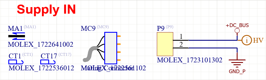
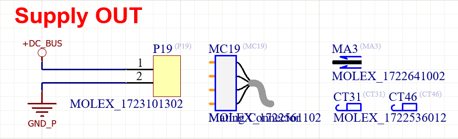
Supply IN and OUT connectors: The selected connectors have a maximum rating of 14 A per circuit and must be changed to others that can support up to 40 A.
|
|
-
TVS protection of the DC bus: The currently selected TVS diode exhibits a leakage current below 1 mA at 60 V and a maximum clamping voltage of 87.1 V. For compatibility with the EVS/EVE drive, the replacement device shall provide a minimum breakdown voltage equal to the new nominal bus voltage of 80 V. Please note that two TVS protection diodes are implemented in the design, one for each axis.
|
Axis A 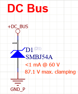
|
Axis B 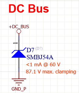
|
-
DC bus decoupling capacitors: As the DC bus voltage increases, the effect of DC bias on the effective capacitance of the decoupling capacitors must be taken into consideration. To select the required bus capacitance for the 45 A current rating, a first-order sizing guideline of 2 μF/A can be applied.
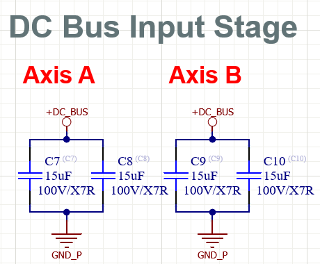
Based on this criterion, the current design, which supports a DC bus current of up to 10 A, requires approximately 20 μF of bus capacitance. When the DC bias derating of the selected capacitors is considered, the effective capacitance decreases to 13.35 μF at 60 V.
-
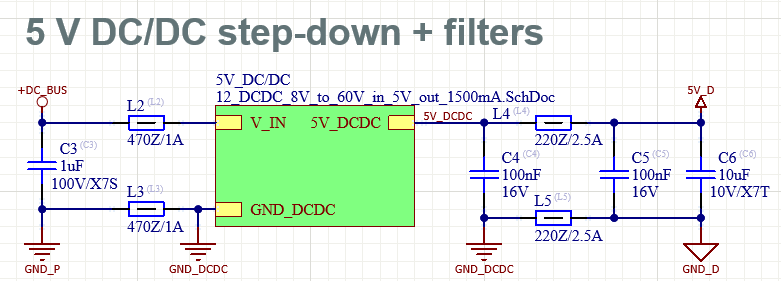
5V DCDC module: The existing 5 V DC/DC converter module is rated for input voltages up to 60 V. To support the new 80 V DC bus, the converter must be redesigned, which requires upgrading the voltage-dependent components, including the input capacitors, MOSFETs, and other associated circuitry.
-
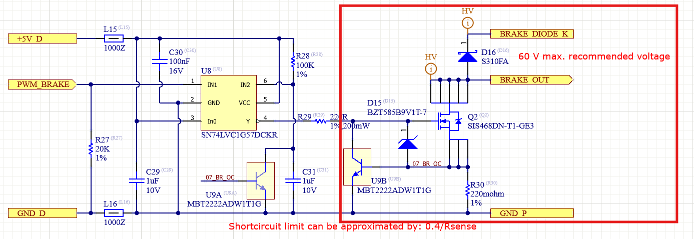
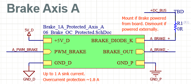
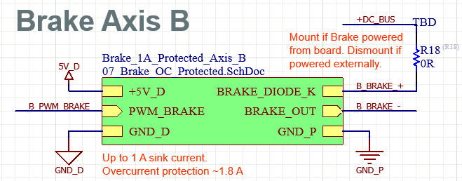
Brake circuit: The brake circuit is currently designed for operation up to 60 V. To accommodate an 80 V DC bus, the following components and circuit sections must be upgraded to meet the higher voltage requirement:
There are two modules present in the design, one per axis:
|
|
-
Inductors at the phases: The currently selected inductors are rated for a maximum continuous current of 10 A. For operation at the 45 A current rating, they must be replaced with components capable of handling at least 45 A without exceeding their thermal and saturation limits.

-
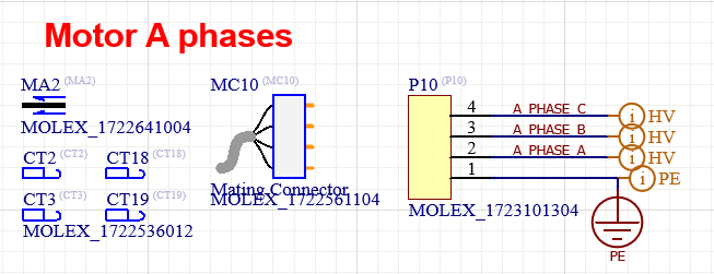
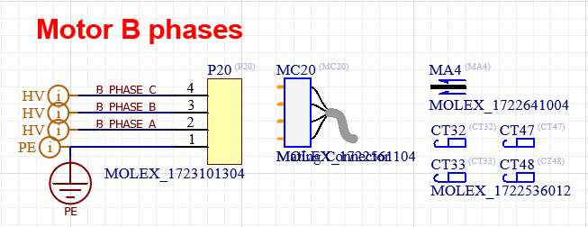
Motor phases connector: Similar to the DC bus input and output connectors, the motor phase connectors must also be replaced with alternatives capable of supporting a continuous current of up to 45 A per pin.
|
|
EVE-NET additional considerations
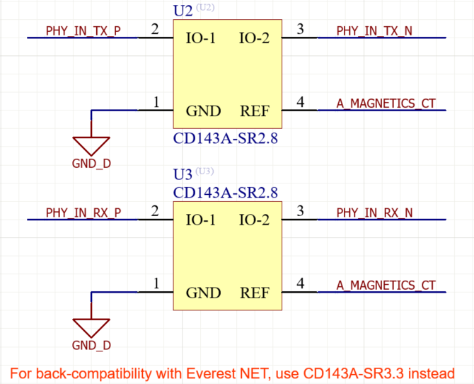
Regardless of whether the board is used solely as an evaluation platform or upgraded to support the full power rating of the EVE-NET drive, the EtherCAT protection components must be replaced accordingly.
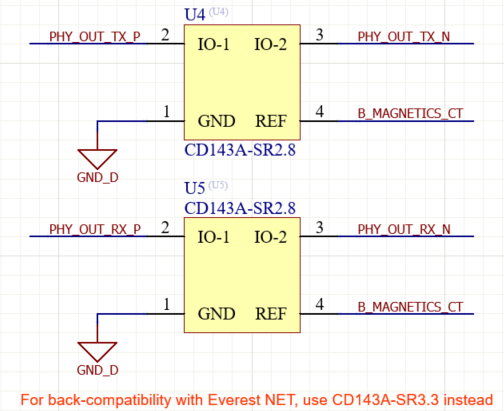
This modification is required because the EVS and CAP drives, due to their lower power consumption, internally set the EtherCAT magnetics center-tap voltage to 1.8 V. In contrast, this is not the case for the EVE-NET drive, where the EtherCAT magnetics center-tap voltage provided by MAGNETICS_CT is 3.3 V.
This difference in the magnetics reference voltage directly requires a corresponding change in the TVS protection circuitry. Therefore, the recommended modification is to replace CD143A-SR2.8 with CD143A-SR3.3.
|
EtherNET input protection |
EtherNET output protection |
|---|---|
|
|
Another significant difference between the EVS/CAP and EVE drives is the feedback connector pinout. To ensure compatibility with the EVE drive, the following modifications must be implemented:
-
Pins 23 and 27: Tie to or pull down to GND_D.
-
Pins 25 and 29: Tie to or pull up to 3.3 V.
-
Pin 40: Configure as ABSENC1DATA only; no MISO connection is present.
-
Pin 41: Leave unconnected (DNC); no MOSI connection is present.