
Everest, Everest S, Capitan, and Denali (EVE, EVS, CAP, DEN) are designed to be interfaced at 5V and 3.3 V levels (or otherwise specified). However, when interfacing other devices, such as sensors, command sources or master controllers, additional adaptor electronics might be required to cover a wider range of input voltages. Here, some circuits are suggested as a reference design for a quick-development of an interface board.
About this solution
Notice this solutions are designed to be simple, cost effective, and easy to manufacture. Other solutions from those presented here may also be valid, and even be more suitable, depending on the approach or design constraints.
Product Manual required
The information presented here is by no means a valid description of the capabilities of each product, but a set of suggestions only. Therefore, it is advised to use this guide together with each drive's specific Product Manual. Particularly, see the Product Description (EVE-NET, EVE-CORE, EVS-NET, EVS-S-NET, CAP-NET, CAP-CORE, DEN-NET, DEN-S-NET) and Pinout (EVE-NET, EVE-CORE, EVS-NET, EVS-S-NET, CAP-NET, CAP-CORE, DEN-NET, DEN-S-NET) sections for the most crucial information on the limits and capabilities of each drive.
Safety considerations
In order to fulfill the safety requirements, the external electronics surrounding the EVS-S/DEN-S drive must comply with specific integration requirements. For more information on the safety-related details, please refer to the Safety Integration chapter.
Wiring information
The scope of this Application Guide is limited to the circuits contained within a hypothetical interface board designed to accommodate the selected drive. However, how this interface board should be connected to the motor, power supplies, and sensors in the final application environment is an equally important consideration. For further guidance, please refer to the Wiring and Connections chapter of the Everest XCR, Everest S XCR, Capitan XCR and Denali XCR Product Manuals, which focuses on the proper wiring practices of Novanta's approach of an NET drive interface board.


Novanta recommends to only select RoHS compliant components for designing products which life cycle can easily adhere to WEEE directive.
Input Supplies
DC Power Supply
Although typically not part of the interface board, but wired outside, this could be one of the main and first elements to take care of, as the way it is dimensioned could affect the rest of the design. The drive generates 3-phase currents by means of an inverter topology power stage, so it require a DC power supply to feed its internal DC bus. Selecting the proper voltage, current and power of this supply is typically not as simple as checking the specifications of the target motor. In fact, in most cases the nominal values of the motor will be substantially different from the analogous values of the power supply. To learn more about this, check out the following documents:
-
Understanding why the motor phase current is different than the power supply current
-
Disambiguation on current values and naming for Novanta Drives
DC Bus Input Stage
Summit Series drives are switched power regulators that use a GaN technology. This allows NET drives to be very efficient, but at the cost of requiring a relatively more sophisticated input stage to avoid transmitting a "sharp" ripple voltage through the power supply lines. This is of an special importance when sharing the DC bus with other sub-systems or when targeting EMC-related certifications, such as CE marking. The most suitable solution will strongly depend on the requirements of:
-
The target market or environment (humanoid, industrial, medical, domestic, automotive...) and the EMC standards that apply to each application.
-
The construction of the motor, specially its inter-winding capacitance and winding-to-chassis capacitance. The lower these capacitances are, the better.
-
The distance between the drive and the motor (length of the phase wires), with the best case being the drive mounted inside the motor metallic housing, which also acts as a "Faraday cage".
-
The voltage and current of the application.
Depending on these parameters the filter can be chosen and tuned, but either way it will typically consist on the following elements:
-
Input power filter
-
Earth decoupling
-
DC bus bulk capacitors
-
Surge / ESD protections
The 2 first elements can be resolved by means of a line filter. A 1-stage line filter might be enough in some cases, but in most cases a 2-stage filter would make it to pass the conducted emissions tests. Anyhow, a line filter might be very bulky compared to the drive, so the on-board discrete solution can be the best trade-off. Here, only very basic and raw indications are given:
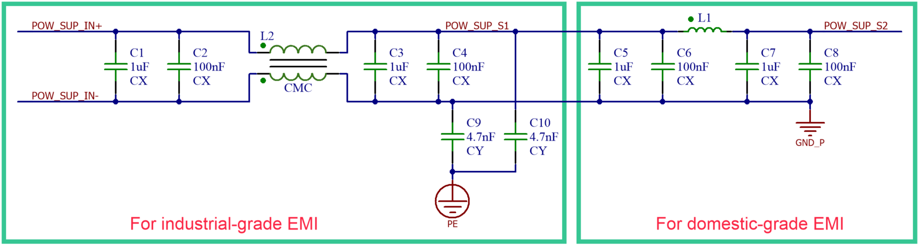
The basic protection to fulfil the minimum requirements of most industrial-grade EMC certifications would consist in a power filter targeting the common mode of the DC bus. The input and output capacitors are separated into 1-decade pairs to extend their effectiveness to higher frequencies (this could be done up to 2 decades or even more). The selected values just pretend to be indicative of this. This capacitors should be of X-type ceramic and their voltage must be carefully selected to match the application under a "safety" criteria: keep in mind that capacity of ceramic capacitors experience a strong derating over voltage. Decoupling capacitors to Earth, represented as C9 and C10 in the above image, are of crucial importance. They must be of Y-type and rated to safety standards, specially when it comes to have its failure mode guaranteed.
For more demanding EMC requirements, like certifications framed in domestic or automotive standards, an additional filter targeting the differential mode might be required. Here a C-L-C or Pi filter is suggested, although many others may be valid. This filter is intended to reduce the voltage ripple in the DC bus caused by the fast commutation of the Drive, as it propagates through the cables affecting both the conduced and radiated frequency ranges. This is strongly related to the load, as inductance and current ratings of the motor directly affect the DC bus voltage ripple, but DC bus bulk capacity plays a notable role in reducing this effect (see below). In any case, selecting an L1 small enough might be demanding, specially when sized to withstand the current ratings of the drive.
Suggested values for inductor L1 may range between 100 nH and 100 µH depending on the conducted EMC requirements. It is typically preferred to increase the DC bus capacitance on the driver side instead of including larger inductance.
Regarding the Common Mode Choke (CMC) L2, a common mode inductance ≥ 1 mH could be a good starting point. Contact Novanta for further help on this topic.
It can also be recommended to split the main power supply into two branches: one dedicated to the drive power stage and motor phases, and another supplying the logic circuitry. Each branch should be equipped with its own EMC filter. This arrangement helps prevent switching noise generated by the power stage from being directly coupled into the logic supply, improving overall system robustness and EMC performance
Second, the DC bus bulk capacity plays a crucial role in the EMI response, but also in the motion control by reducing DC bus ripple. As a dummy rule of thumb, the greater the installed capacity, the better, but at the same time capacitors are big and expensive, so optimising the number and type of the capacitors included in the design is usually something to take care of. Typically, having these capacitors will respond to 3 purposes:
-
Reduce voltage ripple in the DC bus to improve conducted EMI.
-
Reduce voltage ripple in the DC bus to reduce the capacitor's self power losses or the power loss throughout the supply wires.
-
Store excess of energy during regenerative braking.
The solution suggested here does not rely on the DC Bus capacitors to narrow down the regenerative braking issue, provided an specific circuit is proposed to this purpose below in this guide (see the Shunt Braking Resistor Transistor chapter). Then, when it comes to reduce the DC bus voltage ripple, it is interesting to distinguish between 2 phenomena shaping it. In the image below this 2 types of ripple are depicted. The top one has more amplitude, but edges are round and soft, so it mostly carries lower frequency harmonic components. The bottom one has less amplitude, but has sharp edges of a great dV/dt, so it carries higher frequency harmonics. Typically the DC Bus voltage will be affected by this 2 types of ripple, but the magnitude of each will typically depend on the amount of current delivered to the motor, and its phase inductance.
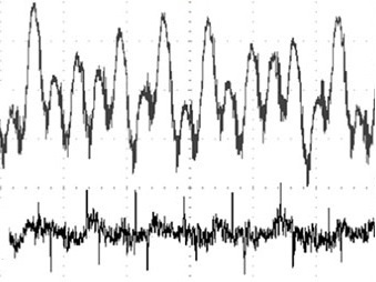
High frequency ripple is more likely to increase when the drive is delivering high phase currents. This ripple does not carry much overall energy but requires capacitors capable of responding to high frequencies with low ESR. Therefore, the best option here are ceramic capacitors, which nowadays typically outperform other capacitor technologies, like tantalum, electrolytic or polymer. Although the minimum required ceramic capacitance is already included within the Summit Series drives, it is strongly recommended to provide additional external ceramic capacitance close to the drive power supply terminals. As a rule of thumb, use approximately 2 µF of X7R/X7S ceramic capacitance per ampere of DC bus current. This recommendation serves as a general guideline; depending on the application requirements and the acceptable DC bus voltage ripple, the total capacitance may be either increased or decreased accordingly.
Low frequency ripple is more likely to increase when the selected motion controller is driving a low inductance motor, especially when driving it at high current. This ripple can arrive to a point where it carries a lot of energy, and therefore a larger capacity would be required. Here, ceramic capacitors are still the best choice, but installing a large bank of ceramic capacity can be space-consuming and very expensive, while electrolytic capacitors, especially aluminum electrolytic capacitors, show much better ratios in capacity per volume at a lower cost. However, be aware that having electrolytic capacitors in a commercial product might entail serious drawbacks: they can contain dangerous chemicals, they can explode if mounted in reverse polarity, they could limit the temperature rating of the whole product, and they would probably become the shortest lifetime component of the design (MTBF bottleneck).
Electrolytic capacitors
Novanta recommends not to use electrolytic capacitors unless there is no other way to satisfy the requirements of an application. In such case, select only the highest quality capacitors, with specs such as:
-
Temperature rating > 100 ºC
-
Low ESR / high ripple withstanding
-
Certified lifetime at high temperature (MTBF) > 6000 hours.
Also, always apply a over-dimension in the voltage rating of electrolytic capacitors of at least x1.3
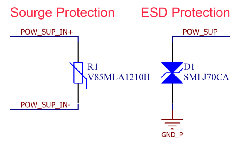
Finally, it is advisable to include surge and ESD protection in the power DC input to reinforce the immunity ratings of the drive. A TVS could do the job for ESD protection, but might be insufficient in front of a surge, where suppression of large but very short power peaks is not as relevant as the response in front of a wide and long high-energy peak. To this purpose, varistors are more suitable. As a useful tip, in case a discrete line filter is implemented, it is recommended to place the TVS after the common mode choke: as a CMC acts like an impedance barrier (from the signals propagation point of view) perturbations in the internal DC bus could become fast and short overvoltages when reflected in the CMC. If any of this reflections reaches a dangerous level, the TVS would get rid of it.
With all this, the following generic solution is proposed:
Schematic
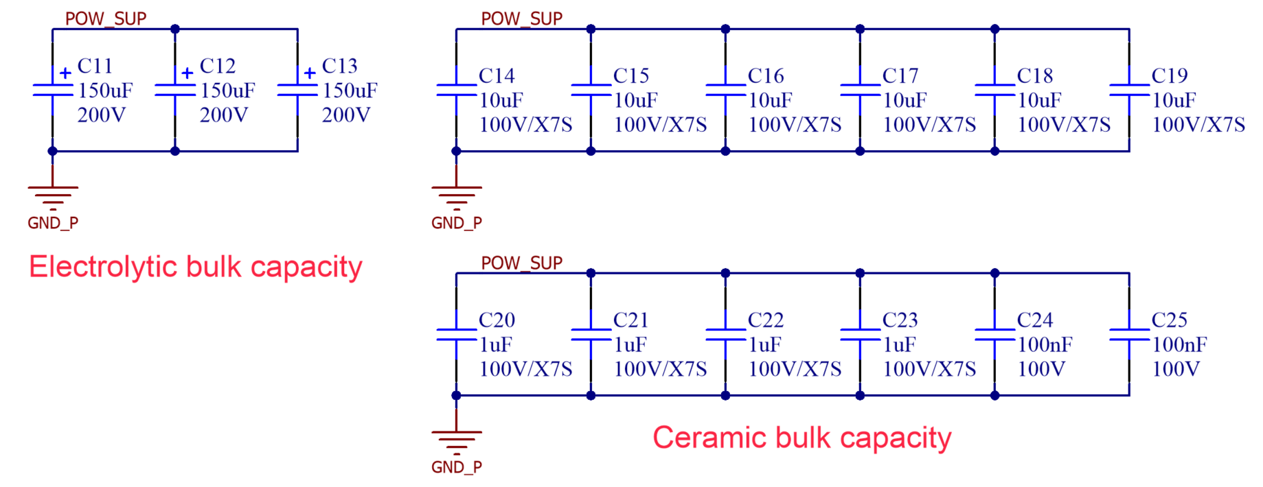
Ceramic and (optional) electrolytic capacitors:
Surge and ESD protection:
Signals description
|
Signal |
Description |
EVE/EVS/EVS-S/CAP pins |
DEN/DEN-S pins |
|---|---|---|---|
|
POW_SUP_IN+ |
Positive terminal of the power supply input |
- |
- |
|
POW_SUP_IN- |
Negative or reference voltage terminal of the power supply input |
- |
- |
|
POW_SUP |
Internal DC bus positive supply. Could be connected to the power pin of the drive if no inverse polarity protection is implemented.
|
The power pin 1 of P1. |
The power pin 2 of P1. |
|
PE |
Protective Earth. Could be left unconnected in specific cases |
To be connected to the chassis. |
The product does not include a chassis as part of the delivered assembly. If an external chassis is incorporated into the final system, the protective earth connection shall be bonded to the chassis. |
|
GND_P |
Internal DC bus reference voltage. |
The power pin 2 of P1 |
The power pin 1 of P1. |
Design Notes
-
POW_SUP net would be connected to POW_SUP_S1 or POW_SUP_S2 depending on the line filter implemented. If no line filter is on-board, it would be connected to POW_SUP_IN+.
-
Select a bidirectional TVS if an inverse polarity protection is implemented (see below), and unidirectional TVS otherwise.
-
Electrolytic capacity would not be required in most cases.
-
Ceramic capacitors should be placed as close to the drive as possible, with the lowest-capacitance capacitors positioned nearest to the P1 pins.
Maximum DC bus supply voltage rating
The TVS diode selected in the example above has a stand-off voltage rating of 70 V rather than 80 V. Consequently, when the DC bus operates at 80 V, approximately 1 mA of leakage current will flow through the device; however, the associated power dissipation is negligible. In return, the lower clamping voltage provides more effective transient suppression, resulting in improved protection of the EVE/EVS drive against overvoltage events.
Bill of materials
|
Designator |
Part Number |
Manufacturer |
Package |
Value / Description |
|---|---|---|---|---|
|
C9, C10 |
GA355DR7GF472KW01L |
Murata |
2220 |
X1/Y2 safety capacitor 4.7 nF -40ºC ~125ºC |
|
L2 |
CM5441Z101B-10 |
Laird |
4 pin Through Hole |
2 Line Common Mode Choke Through Hole 100 Ohms @ 100MHz 75A DCR 0.3mOhm |
|
L1 |
ETQ-P5MR68YLC |
Panasonic |
SMD 10x10mm |
Fixed Inductor 680nH 31.5A 1.93mΩ |
|
C11, C12, C13 |
EKXG201ELL151ML25S |
United Chemi-Con |
Radial, Ø16x25 mm |
Aluminum electrolytic capacitor, 150 µF, 200 V, -40 ºC ~105 ºC, MTBF 1000h @ 105 ºC, 1.89 A @ 100 kHz current ripple |
|
C14, C15, C16, C17, C18, C19 |
C5750X7S2A106K230KB |
TDK |
2220 |
Ceramic capacitor, 10 µF, 100 V, X7S |
|
C1, C3, C5, C7, C20, C21, C22, C23 |
C2012X7S2A105K125AE |
TDK |
0805 |
Ceramic capacitor, 1 µF, 100 V, X7S |
|
C2, C4, C6, C8, C24, C25 |
HMK212B7104KG-T |
TDK |
0805 |
Ceramic capacitor, 100 nF, 100 V, X7R |
|
D1 |
SMLJ70CA |
Bourns |
SMC / DO-214-AB |
Bidirectional diode TVS, 70 V standoff, 113 V max. clamping, 3000 W |
|
R1 |
V85MLA1210H |
LittlelFuse |
1210 |
Varistor, 85 V DC standoff, 250 A max. surge current, 2.5 J max. surge energy |
Logic supply
All Summit Series drives require a regulated 5 V supply with a recommended accuracy of ±2% or less. There are several ways to generate this 5 V rail, and the most suitable approach will typically depend on the available power source from which the logic supply is derived, whether AC or DC. In most applications, the same power supply used for the DC bus will also serve as the source for the logic supply. In such cases, a DC/DC converter should be selected with an input voltage range that accommodates the maximum expected DC bus voltage, including any voltage increase caused by energy regeneration. Typically, this DC/DC converter can be implemented using one of the following three approaches:
-
A discrete DC/DC on board. The converter should be carefully integrated into the PCB layout, following the manufacturer's recommendations regarding critical current paths, particularly the high-side and low-side switching loops, as well as other good design practices commonly associated with power conversion stages.
-
An integrated module mounted into the PCB
-
A completely external DC/DC wired to the Interface Board.
All solutions are valid, providing the following specs are met:
-
Input voltage: determined by the application requirements. A 100 V rating is sufficient for most typical applications, excluding safety-certified systems.
-
Output voltage: +5 V
-
Output voltage regulation: ±2% or less
-
Output voltage rise time: between 2 ms and 10 ms
-
Max. ripple: 200 mVp-p or less
-
Output current: 700 mA continuous, 1 A continuous preferred.
-
Isolation voltage: >1.5 kV recommended to prevent ground loops between digital and power, although not mandatory in some cases.
Novanta is committed to a more efficient use of energy and recommends to always select the highest efficiency components.
Output current required
The minimum output current specified above is only for EVE/EVS/EVS-S/CAP/DEN/DEN-S, so does not include the Interface Board self-consumption or its capability to deliver current to other external circuits.
Initialization sequence
To guarantee all the internal supplies fulfil an adequate power-up sequence, the 5 V supply must reach its nominal voltage in no less than 2 ms and no more than 10 ms. Otherwise, initialization problems could appear, especially at the lowest or highest temperatures. Refer to each product’s manual for specific requirements.
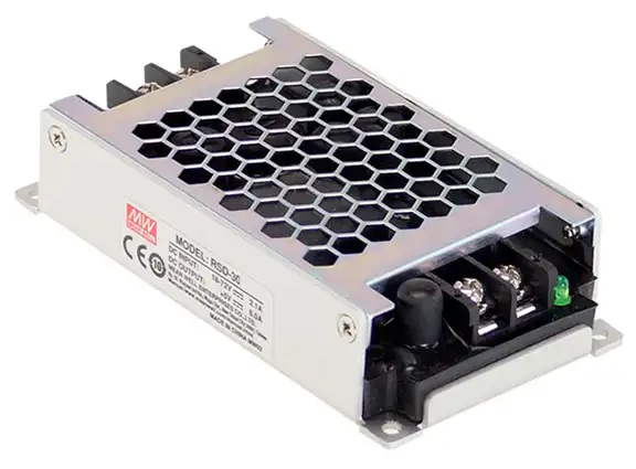
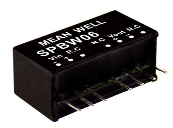
A couple of valid DC/DC examples:
|
Image |
Part Number |
Manufacturer |
Type |
Description |
|---|---|---|---|---|
|
RSD-30H-5 |
Mean Well |
External |
40 V to 160 V input, single 5 V output, 30 W, 4 kV isolation DC/DC |
|
SPBW06G-05 |
Mean Well |
PCB |
18 V to 75 V input, single 5 V output, 6 W, 1.5 kW isolation DC/DC |
Schematic
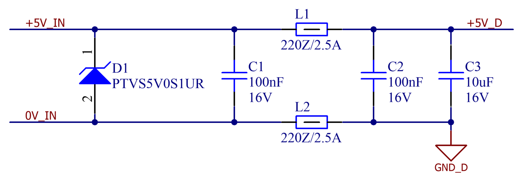
For example, let us assume that the 5 V rail is provided externally. It is recommended that this supply to pass through an input stage incorporating a TVS diode for ESD protection and an input filter. Although a CLC filter could be used, ferrite beads are employed instead of inductors to reduce the required board area and to concentrate the attenuation on higher-frequency noise components.
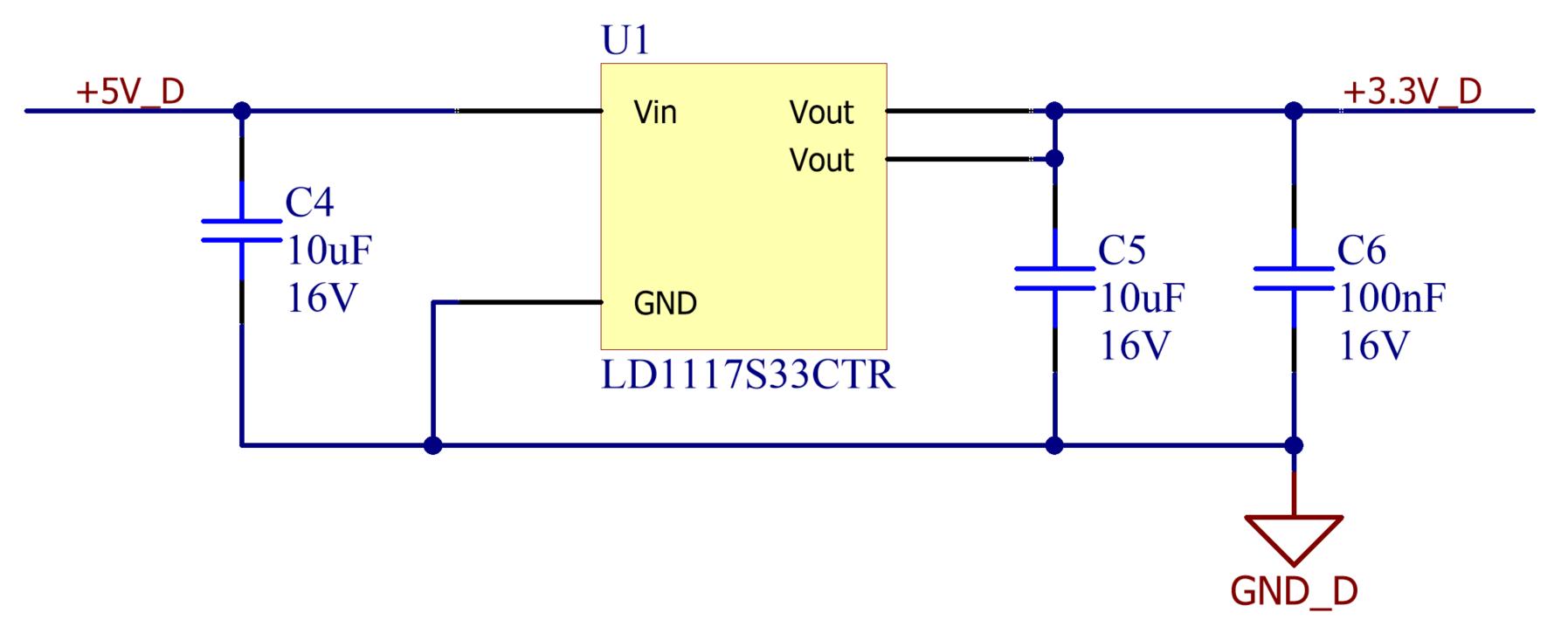
The second stage involves converting the 5 V supply to 3.3 V using a simple LDO.
In the case of EVE/EVS/EVS-S/CAP, the drive does not draw power from the external 3.3 V rail. Consequently, the 3.3 V regulator only needs to supply the interface board's local circuitry and any external devices powered from this rail (refer to the 3.3 V and 5 V Output Supplies chapter for additional details). For applications where the total 3.3 V current consumption remains below 250 mA, the dedicated 3.3 V regulator can be omitted, as the supply may be sourced directly from pin 14 of connector P4 on the EVE/EVS/CAP drive. It should be noted, however, that this capability differs for the EVS-S. While pin 14 of connector P4 also provides a 3.3 V output, the available current is limited to less than 150 mA.
When integrating DEN/DEN-S, the 3.3 V regulator is mandatory, as it is required to supply pin 56 of connector P2.
Signals description
|
Signal |
Description |
EVE/CAP CORE pins |
EVE/EVS/EVS-S/CAP NET pins |
DEN/DEN-S NET pins |
|---|---|---|---|---|
|
+5V_IN |
Positive terminal of the 5 V logic supply input |
- |
- |
- |
|
0V_IN |
Negative terminal of the 5 V logic supply input |
- |
- |
- |
|
+5V_D |
+5 V Logic supply to feed both the drive and the Interface Board. |
Pins 7, 8, 9 and 10 of the Interface connector P4. |
Pins 7, 8, 9 and 10 of the Interface connector P4. |
Pin 58 of the Interface connector P2. |
|
+3.3V_D |
+3.3 V Logic supply to feed the Interface Board. |
If the external peripherals require < 250 mA, pins 9 and 10 of P4 can be used as a 3.3 V power source. Exceeding this limit might cause permanent damage to the drive. Therefore, for higher current demands, a dedicated external 3.3 V regulator must be implemented. In such cases, pins 9 and 10 must not be connected to the external 3.3 V supply rail, as they are intended to operate either as a power source or remain unconnected, but not as inputs. |
Pin 14 of P4 can be used as a 3.3 V power source when the external peripherals require:
Exceeding this limit might cause permanent damage to the drive. Therefore, for higher current demands, a dedicated external 3.3 V regulator must be implemented. In such cases, pin 14 must not be connected to the external 3.3 V supply rail, as they are intended to operate either as a power source or remain uncontered in the Safety Integratnected, but not as inputs. |
When integrating these drives, a dedicated external 3.3 V regulator must be implemented. Pin 56 of the P2 connector acts as a power supply input. In the case of DEN-S NET, pin 23 of connector P2 must also be connected to the 3.3 V rail. Additional information regarding this requirement can be found in the Safety Integration chapter. |
|
GND_D |
Logic supply reference voltage. The selected pins are recommended for DC-DC placement and return path optimization. |
Pins 1, 2, 7 and 8 of the Interface connector P4. |
Pins 5, 6, 11 and 12 of the Interface connector P4. |
Pins 31 (for DEN-S) and 60 of the Interface connector P2. |
Design Notes
-
D1 is a unidirectional TVS, meaning that in case of inverse polarity of the 5 V input this will conduct in direct mode. Then, either the power supply voltage will drop once reached the maximum current or the TVS will burn if the power supply is powerful enough. This behaviour is intended, as it works as a very basic inverse polarity protection in addition to its main ESD protection function.
-
+5V_D must be connected to the dedicated pins of the selected drive's interface connector specified above. All 5 V pins should be connected to ensure sufficient current-carrying capacity through the interface connector contacts. Similarly, all adjacent return pins should be connected to GND_D.
Bill of materials
|
Designator |
Part Number |
Manufacturer |
Package |
Value / Description |
|---|---|---|---|---|
|
C1, C2, C6 |
GRM155R71C104KA88D |
Murata |
0402 |
Ceramic capacitor, 100 nF, 16 V, X7R |
|
C3, C4, C5 |
C2012X7S1C106M125AC |
TDK |
0805 |
Ceramic capacitor, 10 µF, 16 V, X7S |
|
D1 |
PTVS5V0S1UR,115 |
NXP |
SOD-123W |
Unidirectional diode TVS, 5 V standoff, 9.2 V max. clamping, 400 W |
|
L1, L2 |
BLM18SG221TN1D |
Murata |
0603 |
2.5 A ferrite bead, 220 Ω @ 100 MHz, 40 mΩ @ DC |
|
U1 |
LD1117S33CTR |
ST Microelectronics |
SOT-223-4N |
15 V max. input LDO, fixed 3.3V output, 800 mA |
Digital and Analog grounds disambiguation
Summit series drives (except DEN/DEN-S NET) have different reference nets for the digital ground (GND_D) and analog ground (GND_A).
Use GND_D as reference for all digital circuits.
Use the GND_A as the reference ground for your analog circuits.
GND_D and GND_A connection
Nets GND_D and GND_A are internally connected using a ferrite bead.
-
If analog signals are not used, do not connect GND_A on your board.
-
If analog signals are used, do not connect GND_D and GND_A directly. Use a ferrite bead or 1 Ω resistor in between.
Protective circuits
Inverse Polarity Protection
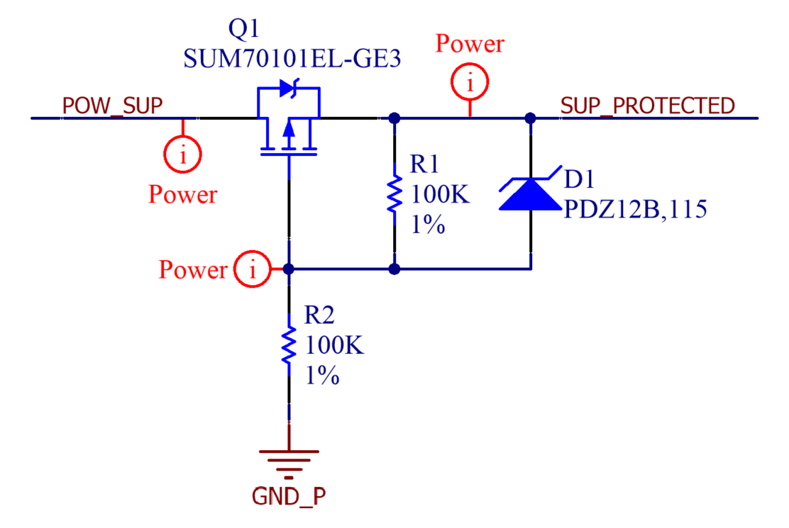
This circuit is intended to block any current going into the drive when the power supply is connected in inverted polarity. If this circuit is not present, it is suggested to select a polarized power supply connector.
Effects of inverted polarity
Connecting the power supply under inverted polarity with no protection could cause permanent damage to drive.
Schematic
Signals description
|
Signal |
Description |
EVE/EVS/EVS-S/CAP pins |
DEN/DEN-S pins |
|---|---|---|---|
|
POW_SUP |
Input from power supply |
- |
- |
|
SUP_PROTECTED |
Protected power supply. |
The power pin 1 of P1. |
The power pin 2 of P1. |
|
GND_P |
Power supply reference voltage. |
The power pin 2 of P1 |
The power pin 1 of P1. |
Design Notes
-
In this circuit, the P-channel MOSFET is only polarized properly when the polarity of the supply is correct thanks to resistors R1 and R2. Diode D1 ensures that the maximum gate voltage of the transistor is not exceeded.
-
Note that the transistor orientation intentionally allows conduction through the body diode if the supply is polarised properly.
Bill of materials
|
Designator |
Part Number |
Manufacturer |
Package |
Value / Description |
|---|---|---|---|---|
|
D1 |
PDZ12B,115 |
NXP |
SOD-323 |
Diode Zener 12 V, 400 mW, 2% tolerance |
|
Q1 |
SUM70101EL-GE3 |
Vishay |
TO-263 / D2PAK |
P-channel MOSFET, 100 V, 120 A |
|
R1, R2 |
RMCF0402FT100K |
Stackpole |
0402 |
Thick film resistor, 100 kΩ, 1 % tolerance, 1/16 W |
Shunt Braking Resistor Transistor
During operation the motor normally consumes the energy provided by the drive, but in specific situations this roles change and the motor behaves as a generator. This would happen during short periods of time when the motor is commanded to rapidly decelerate or even change its direction of rotation, or during longer periods of time when the load is driving the motor, like it would happen when a hoist is overloaded. In this cases, although an inverter typically works as a "step-down", it will behave as a "step-up", and could elevate the voltage of the internal DC bus even beyond its maximum ratings, causing permanent damage to the drive and leaving the load completely uncontrolled.
Therefore, this is an over-voltage protection.
To get rid of the problem, 4 strategies are considered. The best one to follow would mostly depend on the dynamics of the load, so there is not a best solution to frame all the possible scenarios.
-
Not doing anything: re-injection could not be an issue, specially when the nominal voltage of the motor is way smaller than the one of the drive (i.e. driving a 24 V motor with EVE/CAP drive). If the re-injection is not too strong, the internal DC bus of the drive will increase, but not enough to reach dangerous levels, so the drive will simply withstand it.
-
Using the DC bus capacitors: if a large bulk capacity is installed close to the drive (not long wires between them) when the DC bus voltage increases because of a re-injection, the capacitors will store the energy, and slowly deliver it afterwards to the motor during normal operation. This method is tremendously ineffective compared to dissipating the excess of energy, but it could do the job in front of short and fast re-injections that would not happen very often, like when the motor sporadically has to change direction of rotation .
-
The system is battery powered: in this specific case, the re-injection charges the battery. In some applications, like electric vehicles, this might even be an advantage, as it would extend the battery life. However, care must be taken in ensuring that the re-injected current measured in the battery terminals is not beyond its maximum charging ratings. Also, when the battery is fully charged this method cannot be used.
-
Get rid of the excess of energy: Here a transistor is used to short the DC bus to Ground through a power resistor, which would dissipate the excess of energy as heat. This method has proved to be the most effective (and the less efficient) but has the drawback of requiring a very bulky resistor, which is costly and space-consuming. This method can be implemented with the circuit proposed below.
To learn more about motor re-injection and how to dimension the power resistor, check the following document:
Multi-axis systems
Notice that in multi-axis systems or even when multiple drives share a same DC bus only 1 braking resistor is needed. Even some advanced power supplies have a braking resistor already integrated.
Schematic
Signals description
|
Signal |
Description |
EVE/CAP CORE pins |
EVE/EVS/EVS-S/CAP NET pins |
DEN/DEN-S NET pins |
|---|---|---|---|---|
|
+5V_D |
+5 V Logic supply |
- |
- |
- |
|
OVERVOLTAGE |
To be connected to any of the GPOx pins. The desired functionality must be configured through the corresponding GPIO registers in the drive. |
The available pin options are pins 43, 55, 56 or 57 on the P4 interface connector. |
The available pin options are pins 17, 29, 30 or 31 on the P4 interface connector. |
The available pin options are pins 26 or 28 on the P2 interface connector. |
|
SUP_PROTECTED |
To be connected to power. |
The power pin 1 of P1. |
The power pin 1 of P1. |
The power pin 2 of P1. |
|
BR- |
To be connected to the negative terminal of the power resistor |
- |
- |
- |
|
GND_P |
Power supply reference voltage. |
The power pin 2 of P1 |
The power pin 2 of P1 |
The power pin 1 of P1. |
|
GND_D |
Logic supply reference voltage. Pins close to the selected GPOx for overvoltage monitoring. |
Could be connected to pin 39, 59 or 60 of the P4 interface connector. |
Could be connected to pin 15, 35 or 38 of the P4 interface connector. |
Could be connected to pin 31 on the P2 interface connector. |
Design Notes
-
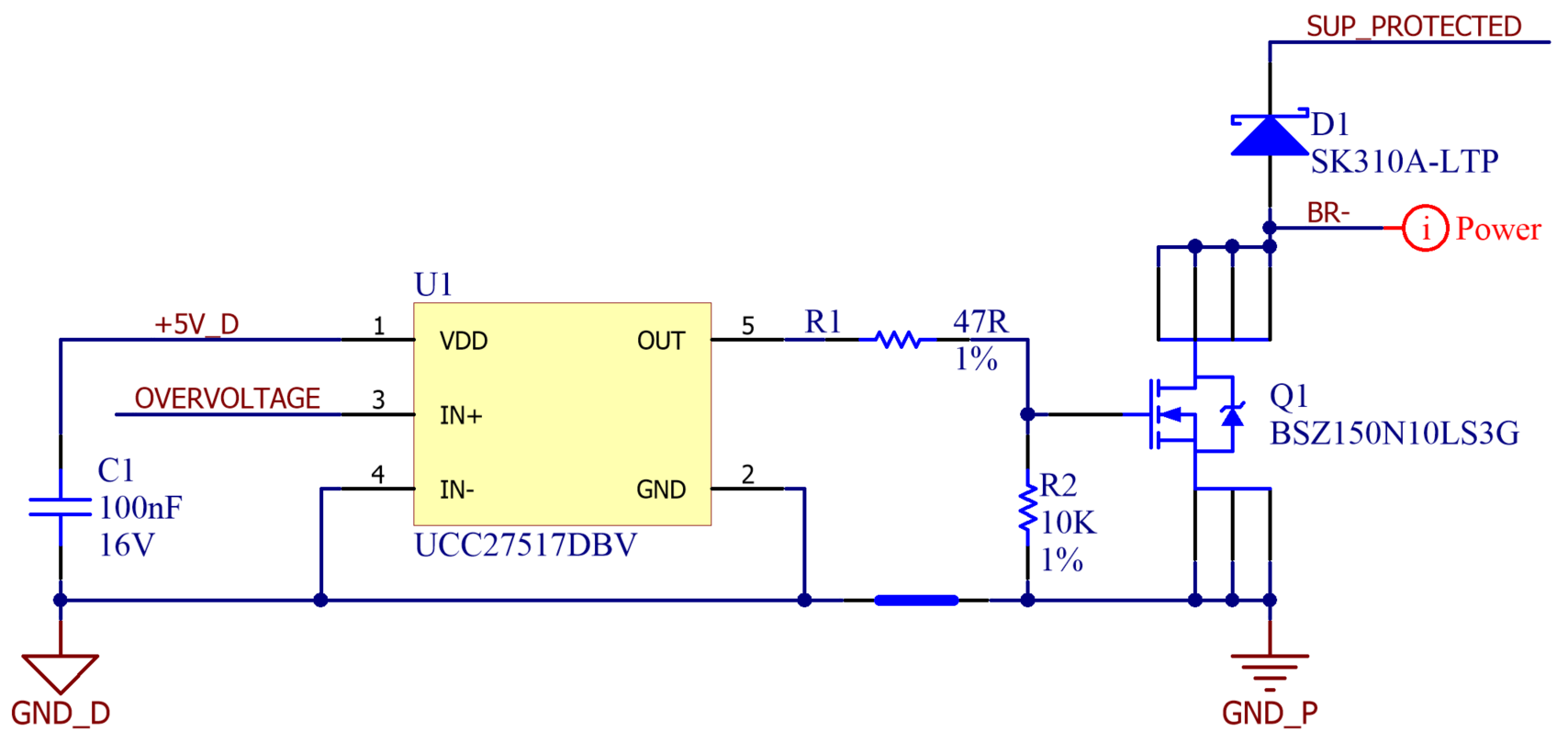
OVERVOLTAGE net must be tied to any of the GPOx pins of EVE/CAP Interface connector (above specified pins based on the product version used). Then, the drive must be configured to map the Overvoltage signaling functionality to this specific GPO, which will then stop working as a general-purpose digital output. Check out the Summit Series Reference Manual to know how to configure this feature.
-
Connect this protection as close to the drive as possible. If an Inverse Polarity Protection is also implemented, connect their SUP_PROTECTED nets together.
-
The positive terminal of the power resistor could be connected to SUP_PROTECTED net or externally to the positive terminal of the power supply.
-
The net-tie between the GND_D and the GND_P allows sharing the same reference voltage while controlling the return path in the layout phase.
-
C1 is a decoupling capacitor for U1.
-
3.3 V could be enough to excite the gate of Q1, although at least 4.5 V is recommended to reduce power losses. In any case, it is not recommended to drive Q1 directly from a GPOx pin of the drive.
-
The wheeling diode D1 provides a discharge path for the energy stored in the power resistor (specially for wirewound type of resistor).
Commutation requirements
Once a power resistor is properly selected, meaning that it fits the dynamics of the load during re-injection, there is no need to modulate the excitation of Q1. Not only no PWM is required, but it would even have a negative effect by increasing the power losses in the transistor with no need. Still, the transistor will switch at a frequency within the scale of 10 Hz to 1 kHz, depending on the over-voltage detection hysteresis configured in the drive.
Bill of materials
|
Designator |
Part Number |
Manufacturer |
Package |
Value / Description |
|---|---|---|---|---|
|
C1 |
GRM155R71C104KA88D |
Murata |
0402 |
Ceramic capacitor, 100 nF, 16 V, X7R |
|
D1 |
SK310A-LTP |
Micro Commercial |
SMA / DO-214AC |
Diode Schottky, 3 A, 100 V |
|
Q1 |
BSZ150N10LS3 G |
Infineon |
TSDSON-8 |
Logic-level N-Channel MOSFET, 100 V, 40 A |
|
R1 |
CRCW040247R0FKEDHP |
Vishay |
0402 |
Thick film resistor, 47 Ω, 1 % tolerance, 1/5 W |
|
R2 |
RMCF0402FT10K0 |
Stackpole |
0402 |
Thick film resistor, 10 kΩ, 1 % tolerance, 1/16 W |
|
U1 |
UCC27517DBVT |
Texas Instruments |
SOT-23-5 |
Low-side gate driver, 18 V, 4 A peak |
Safe Torque Off (STO)
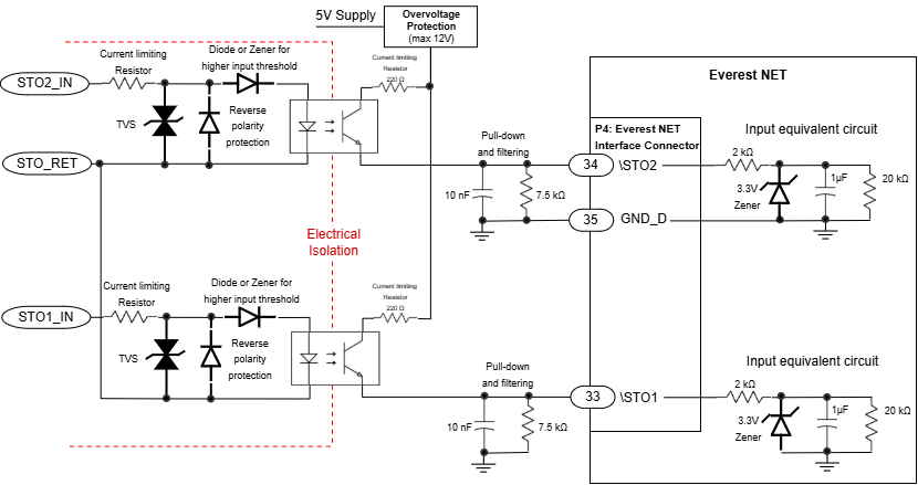
This circuit provides a dual-channel, protected, and isolated input interface for the Safe Torque Off (STO) safety function built into the drive. If the STO inputs are not energized, the transistors of the power stage are turned off and an STO fault is notified. In order to activate the power stage, and therefore allow the motor operation, the two STO inputs must be energized. STO inputs should not be confused with a digital input configured as enable input, because enable input is firmware controlled and does not guarantee intrinsic safety as it can be reconfigured by a user.
This does not apply to EVS-S nor DEN-S products. In these products, the equivalent signals are “Safe Inputs”, not direct STO inputs. The main difference is that, in the classical NET drive, the STO entries are dedicated hardware inputs that act directly on the Safe Torque Off function. In the EVS-S-NET and DEN-S-NET drives, the signals are safety-rated inputs that are configured by the Safety Master and read by the SaCo; their behavior is then assigned to the required safety function, such as STO or SS1-t, through the certified safety configuration. Therefore, they should not be treated as simple STO enable lines, but as part of the drive’s safety-control architecture and its corresponding integration requirements. For more information please check the Safety Integration chapter within the Application Guide.
Circuit Diagram
The following circuit represents one possible implementation that satisfies the integration requirements; however, alternative solutions may also be used.
Signals description
|
Signal |
Description |
EVE/CAP CORE pins |
EVE/EVS/EVS-S/CAP NET pins |
DEN/DEN-S pins |
|---|---|---|---|---|
|
+5V |
+5V Logic supply |
- |
- |
- |
|
+5V_PROT |
+5V supply protected. Output voltage cannot exceed 12V in the event of a single failure. |
- |
- |
- |
|
STO1_IN |
Safe Torque Off inputs positive terminal |
- |
- |
- |
|
STO2_IN |
||||
|
STO_RET |
Safe Torque Off inputs negative or reference terminal |
- |
- |
- |
|
\STO1 |
To be connected to the Interface connector |
Pin 33 of connector P4. |
Pin 33 of connector P4. |
Pin 13 of connector P2. |
|
\STO2 |
To be connected to the Interface connector |
Pin 34 of connector P4. |
Pin 34 of connector P4. |
Pin 17 of connector P2. |
|
GND_D |
Logic supply reference voltage. |
Pin 32 of connector P4. |
Pin 35 of connector P4. |
Pin 15 of connector P2. |
Design Notes
-
STO_RET is tied together from the 2 circuits, but could be wired separately.
Not using STO
When STO inputs are not required, the \STO1 and \STO2 signals must be tied directly to a logic-high level. The +5 V supply is the preferred option; however, +3.3 V may also be used.. In this case, do not use a series or pull-up resistor; connect the signals directly to the selected supply rail.
Functional Safety Certification Other drives
The use of galvanic isolation in the STO interface is not always mandatory and depends on the origin of the STO signals as well as the ability of the overall system design to meet the applicable safety integration requirements. When the STO signals are generated by a safety controller or other safety-related electronics located on the same PCB, an isolated interface may not be required. However, when the STO signals originate from external devices connected through long cables, such as an emergency stop pushbutton, galvanic isolation is typically recommended to ensure robust operation and compliance with safety requirements.
Depending on the used drive, each has its own functional safety certification. To achieve the required Safety Integrity Level, all integration requirements must be strictly fulfilled. Refer to the table below, which provides links to additional information for each product.
|
Product |
Compliance |
Safety Manual for Safe Torque Off (STO) |
|---|---|---|
|
EVE-CORE |
||
|
EVE-NET |
||
|
EVS-NET |
||
|
EVS-S-NET |
||
|
CAP-CORE |
||
|
CAP-NET |
||
|
DEN-NET |
||
|
DEN-S-NET |
Inputs and Outputs
Digital Inputs
Since the drive uses 3.3 V logic levels, the following circuits provide simple methods for interfacing a wide range of input voltages.
Schematic
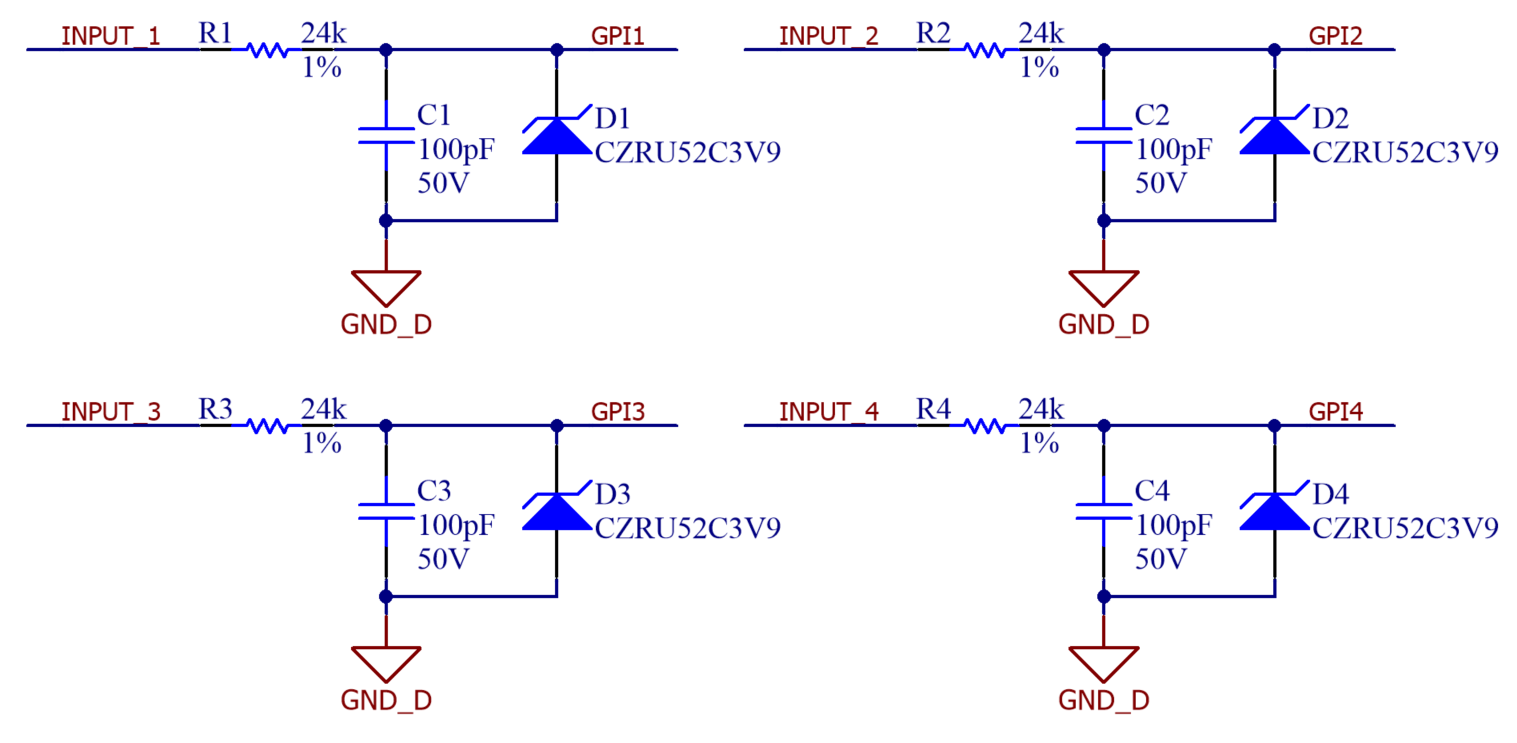
A resistor limits the current while a Zener diode saturates the voltage. The drive will detect as "low" any voltage lower than 0.8, and as "high" any voltage greater than 3 V, while still being tolerant to input voltages up to 30 V.
Signals description
|
Signal |
Description |
EVE/CAP CORE pins |
EVE/EVS/EVS-S/CAP NET pins |
DEN/DEN-S pins |
|---|---|---|---|---|
|
INPUT_1 |
Digital inputs 1 to 4
|
- |
- |
- |
|
INPUT_2 |
||||
|
INPUT_3 |
||||
|
INPUT_4 |
||||
|
GPI1 |
To be connected to the Interface connector. |
Pin 47 of connector P4. |
Pin 18 of connector P4. |
Pin 22 of connector P2. |
|
GPI2 |
To be connected to the Interface connector. |
Pin 49 of connector P4. |
Pin 19 of connector P4. |
Pin 24 of connector P2. |
|
GPI3 |
To be connected to the Interface connector. |
Pin 53 of connector P4. |
Pin 20 of connector P4. |
- |
|
GPI4 |
To be connected to the Interface connector. |
Pin 58 of connector P4. |
Pin 32 of connector P4. |
- |
|
GND_D |
Logic supply reference voltage. |
Pin 59 or 60 of connector P4. |
Pin 15, 16 or 35 of connector P4. |
Pin 15 or 31 of connector P2. |
Design Notes
-
For simplicity, the proposed solution is not opto-isolated. Therefore, the input signals generator (could be a PLC or other controller) must share the Ground with drive.
-
24 kΩ is not a random value. It is intended to fit the voltage-current characteristic curve of the Zener diodes.
-
Capacitors form a 1st order filter with the resistors. This will typically reject high-frequency noise coupled to the wiring in most of the cases.
Bill of materials
|
Designator |
Part Number |
Manufacturer |
Package |
Value / Description |
|---|---|---|---|---|
|
R1, R2, R3, R4 |
RC0603FR-0724KL |
Yageo |
0603 |
Thick film resistor, 24 kΩ, 1 % tolerance, 0.1 W |
|
C1, C2, C3, C4 |
CC0402JRNPO9BN101 |
Yageo |
0402 |
Ceramic capacitor, 100 pF, 50 V, NP0 |
|
D1, D2, D3, D4 |
CZRU52C3V9 |
Comchip |
0603 |
Diode Zener 150 mW 5% 0603. 3.9 V @ 5mA, 3.3 V @ 1mA |
Digital Outputs
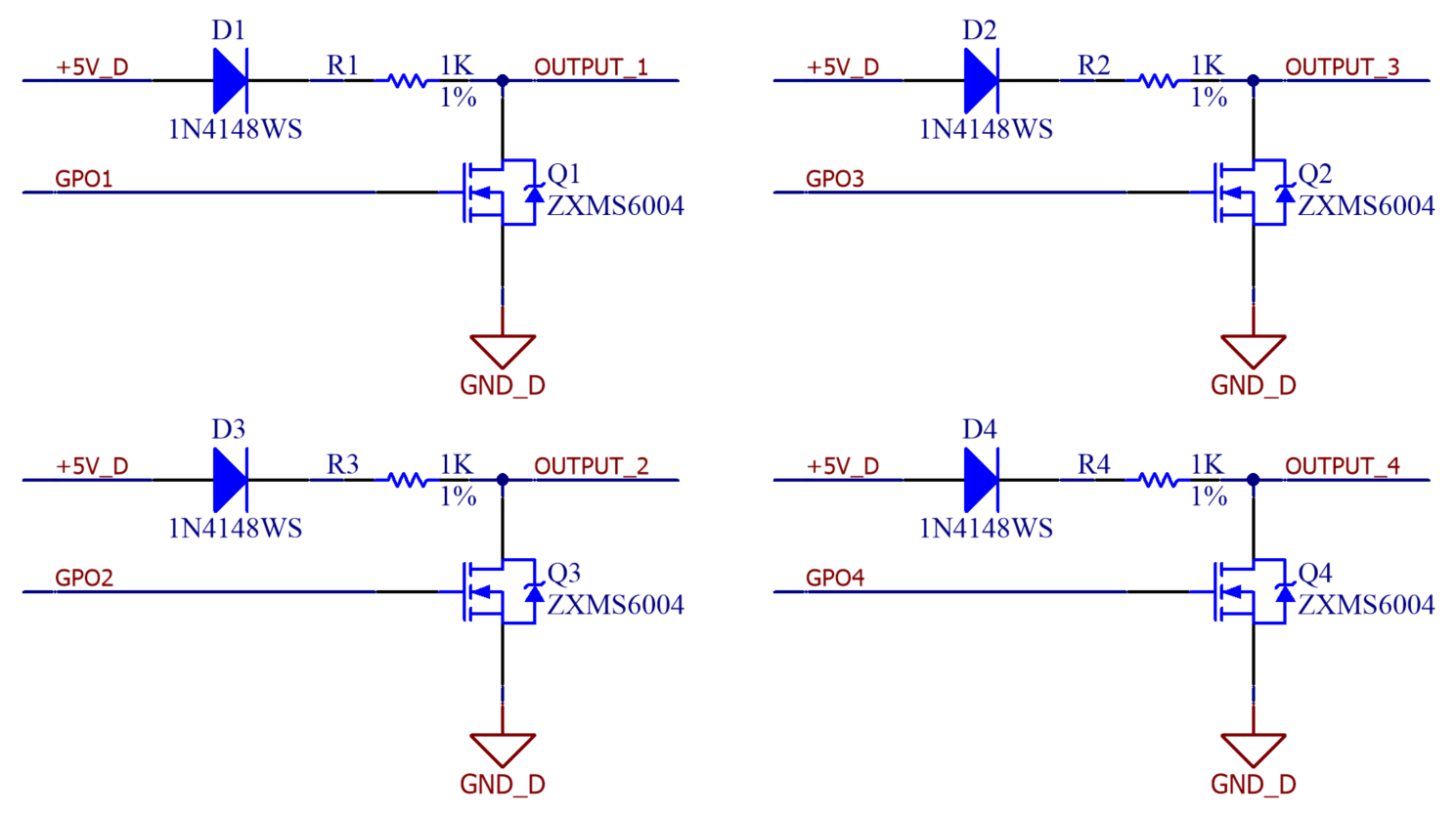
This simple circuit can be used to convert the selected drive's 3.3 V push-pull digital outputs into 5 V open-collector outputs with weak pull-up resistors. Although the circuit inverts the output logic polarity, it also enables the output to drive higher-current loads than would be possible with the drive's native output stage.
Schematic
The following circuits should allow driving loads up to 48 V and 1 A safely.
Signals description
|
Signal |
Description |
EVE/CAP CORE pins |
EVE/EVS/EVS-S/CAP NET pins |
DEN/DEN-S pins |
|---|---|---|---|---|
|
+5V_D |
+5 V Logic supply |
- |
- |
- |
|
OUTPUT_1 |
Digital outputs 1 to 4 |
- |
- |
- |
|
OUTPUT_2 |
||||
|
OUTPUT_3 |
||||
|
OUTPUT_4 |
||||
|
GPO1 |
To be connected to the Interface connector. |
Pin 55 of connector P4. |
Pin 29 of connector P4. |
Pin 26 of connector P2. |
|
GPO2 |
To be connected to the Interface connector. |
Pin 56 of connector P4. |
Pin 30 of connector P4. |
Pin 28 of connector P2. |
|
GPO3 |
To be connected to the Interface connector. |
Pin 57 of connector P4. |
Pin 31 of connector P4. |
- |
|
GPO4 |
To be connected to the Interface connector. |
Pin 43 of connector P4. |
Pin 17 of connector P4. |
- |
|
GND_D |
Logic supply reference voltage. |
Pin 39, 59 or 60 of the P4 interface connector. |
Pin 15, 35 or 38 of the P4 interface connector. |
Pin 31 on the P2 interface connector. |
Design Notes
-
The suggested MOSFETs do not require gate biasing.
-
Also, the suggested MOSFETs feature short-circuit, overload, over-temperature and inverse polarity protection.
-
This solution should allow driving small inductive loads with no need of a wheeling diode.
-
When driving loads in open collector configuration, only the negative terminal of the load must be connected to the output. Although it is an output, it will work by sinking current. The positive terminal of the load would be connected to a power source which Ground terminal is shared with the drive.
-
When using the load in push-pull configuration, the 1 kΩ resistor set the output impedance and limit the current. In this case, note that the polarity of the GPOx signal coming from the drive will be inverted in the output.
Bill of materials
|
Designator |
Part Number |
Manufacturer |
Package |
Value / Description |
|---|---|---|---|---|
|
D1, D2, D3, D4 |
1N4148WS |
Fairchild |
SOD-323F |
Diode rectifier 75 V, 150 mA |
|
R1, R2, R3, R4 |
RMCF0402FT1K00 |
Stackpole |
0402 |
Thick film resistor, 1 kΩ, 1 % tolerance, 1/16 W |
|
Q1, Q2, Q3, Q4 |
ZXMS6004FFTA |
Diodes Inc. |
SOT-23F |
N-channel MOSFET , 60 V, 1.3 A |
Mechanical Brake Output
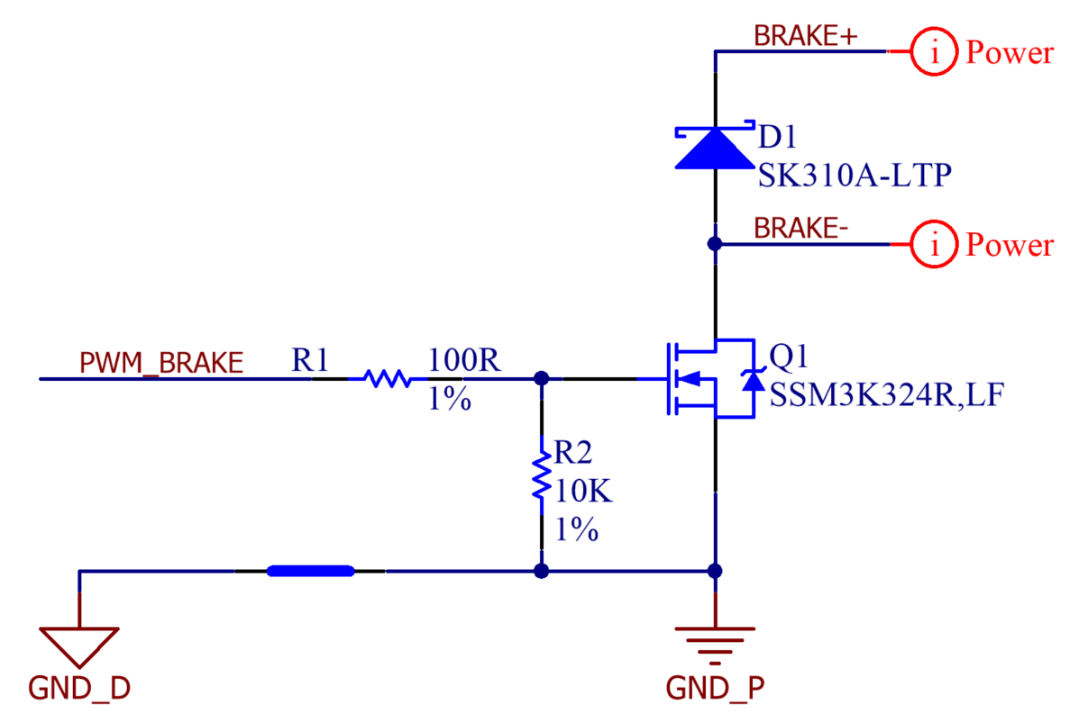
Because of its similarities, the same circuit as the one proposed in the Shunt Braking Resistor Transistor section could be used. However, for cost and space optimisation, the following circuit is proposed. This would provide a 24 V tolerant open collector output for driving a mechanical brake of the solenoid type.
Schematic
Signals description
|
Signal |
Description |
EVE/CAP CORE pins |
EVE/EVS/EVS-S/CAP NET pins |
DEN/DEN-S pins |
|---|---|---|---|---|
|
BAKE+ |
Positive terminal of the brake solenoid |
- |
- |
- |
|
BAKE- |
Negative terminal of the brake solenoid |
- |
- |
- |
|
PWM_BRAKE |
To be connected to the Interface connector. |
Pin 42 of connector P4. |
Pin 41 of connector P4. |
Pin 30 of connector P4. |
|
GND_D |
Logic supply reference voltage. |
Pin 39 of connector P4. |
Pin 38 of connector P4. |
Pin 31 of connector P4. |
|
GND_P |
Power supply reference voltage. |
The power pin 2 of P1 |
The power pin 2 of P1 |
The power pin 1 of P1. |
Design Notes
-
Signal BRAKE+ is to be connected to the positive terminal of the brake solenoid, and at the same time to the positive terminal of the brake power supply. The negative terminal of the brake power supply must be tied to GND_P.
-
If the DC bus is supplied at 24 V or less, the signal BRAKE+ could be tied to SUP_PROTECTED or externally connected to the positive terminal of the power supply.
-
The net-tie between the GND_D and the GND_P allows sharing the same reference voltage while controlling the return path in the layout phase.
-
As a solenoid is a highly inductive load, the wheeling diode D1 provides a discharge path for the energy stored in it.
In case of a low voltage DC bus
The drive DC bus can be driven from a very low voltage power supply, but still a 24 V brake might be required. In the event that the DC bus is lower than the brake driving voltage, the signal BRAKE+ must not be tied to the DC bus (either SUP_PROTECTED, POW_SUP or power pin of P1 connector of the drive). If doing so, diode D1 would short the DC bus to a greater voltage, allowing a great current through it, and most probably burning it.
Bill of materials
|
Designator |
Part Number |
Manufacturer |
Package |
Value / Description |
|---|---|---|---|---|
|
D1 |
SK310A-LTP |
Micro Commercial |
SMA / DO-214AC |
Diode Schottky, 3 A, 100 V |
|
Q1 |
SSM3K324R,LF |
Toshiba |
SOT-23-3N |
Logic-level N-Channel MOSFET, 30 V, 4 A |
|
R1 |
RMCF0402FT100R |
Stackpole |
0402 |
Thick film resistor, 100 Ω, 1 % tolerance, 1/16 W |
|
R2 |
RMCF0402FT10K0 |
Stackpole |
0402 |
Thick film resistor, 10 kΩ, 1 % tolerance, 1/16 W |
Motor Temperature Input
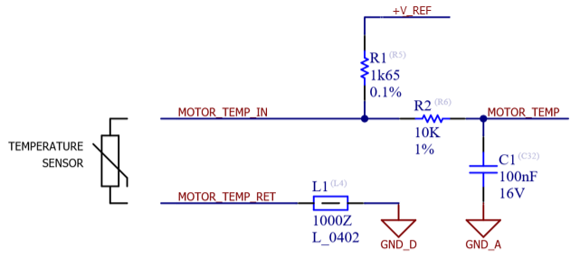
The drives allow the connection of an external motor temperature sensor, typically a 2-wire sensor based on changes of resistance (PTC thermistor, bimetal, NTC, PT100, silicon temperature sensors).
Schematic
Simple but effective signal conditioning can be done with a voltage divider, a low-pass filter and a ferrite bead for decoupling.
Signals description
|
Signal |
Description |
EVE/CAP CORE pins |
EVE/EVS/EVS-S/CAP NET pins |
DEN/DEN-S pins |
|---|---|---|---|---|
|
MOTOR_TEMP_IN |
Positive terminal of the external temperature sensor. |
- |
- |
- |
|
MOTOR_TEMP_RET |
Negative terminal of the external temperature sensor. |
- |
- |
- |
|
MOTOR_TEMP |
To be connected to the respective Feedback/Interface connector. |
Pin 13 of connector P3. |
Pin 13 of connector P3. |
Pin 16 of connector P2. |
|
+V_REF |
Logic supply, either +5 V or +3.3 V, depending on the integrated drive. |
Connected to +5V_D. |
Connected to +5V_D. |
Connected to +3.3V_D. |
|
GND_D |
Logic supply reference voltage. To be connected to the Interface connector. |
Pins 1 or 2 of the P4. |
Pins 5 or 6 of the P4. |
Pin 15 of connector P2. |
|
GND_A |
Analog reference voltage (if present in the selected drive for integration). |
Pin 20 of connector P3. |
Pin 20 of connector P3. |
Non-existing pin, connect to the same GND_D pin 15 of connector P2. |
Design Notes
-
It is recommended to decouple the motor temperature return (MOTOR_TEMP_RET) to GND_D instead to GND_A for better EMI performance.
-
A different pull-up voltage (+V_REF in the schematic) can be used, but 5 V in EVE/EVS/EVS-S/CAP and 3.3 V in DEN/DEN-S, provides the maximum resolution. Pull-up voltage must be configured in the firmware register "0x110 - Motor temperature sensor voltage reference". Further information on Summit Reference Manual, section Motor and brake.
-
Pull-up resistor must be configured in the firmware register "0x210D - Motor temperature sensor external resistance". Further information on Summit Reference Manual, section Motor and brake
Bill of materials
|
Designator |
Part Number |
Manufacturer |
Package |
Value / Description |
|---|---|---|---|---|
|
R1 |
CPF0402B1K65E1 |
TE Connectivity |
0402 |
Thin film resistor, 1.65 kΩ, 0.1 % tolerance, 1/16 W |
|
R2 |
RMCF0402FT10K0 |
Stackpole Electronics |
0402 |
Thick film resistor, 10 kΩ, 1 % tolerance, 1/16 W |
|
C1 |
GRM155R71C104KA88D |
Murata Electronics |
0402 |
Ceramic capacitor, 100 nF, 16 V, X7R |
|
L1 |
MMZ1005S102CT000 |
TDK Electronics |
0402 |
Signal Line Ferrite Bead 1 kOhms @ 100MHz |
Output Supplies
3.3 V and 5 V Output Supplies
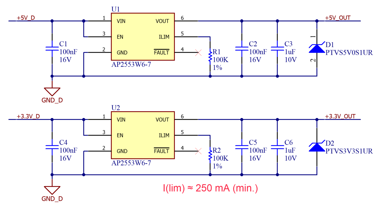
To be able of supplying external circuitry, like feedback sensors or command sources, two load switches are implemented as identical circuits. This would limit the current drawn from the outside, providing both short-circuit and overload protection, and thus maintaining the internal logic supply lines safe. Additionally, TVS diodes are added for ESD protection.
External current consumption
Both 5 V and 3.3 V internal logic supplies must be able of handling the self-consumption plus the maximum current limit set here. Otherwise the internal logic supplies could drop before the load switch overcurrent protection acts, which could cause failures of diverse nature. See Logic supply chapter above for more information.
GND connection required
External circuitry supplied this way must have its reference or Ground voltage connected to GND_D
Schematic
Signals description
|
Signal |
Description |
|---|---|
|
+5V_D |
+5 V internal Logic supply |
|
+3.3V_D |
+3.3 V internal Logic supply |
|
+5V_OUT |
+5 V output supply for external circuits |
|
+3.3V_OUT |
+3.3 V output supply for external circuits |
|
GND_D |
To be connected to GND_D of the drive Interface connector. |
Design Notes
-
R1 and R2 set the current limit. Considering the tolerances of both the load switch and the resistor, the current would be limited to a minimum of 246 mA and a maximum of 315 mA, with a typical value of 282 mA. Thermal drifts are not considered in this calculation.
-
This approach provides a quite rugged overcurrent protection, but it is very weak in front of overvoltage. Any voltage over 6.5 V in the output might cause permanent damage to the load switch. TVS will help here, put not to become an overvoltage protection in DC.
Bill of materials
|
Designator |
Part Number |
Manufacturer |
Package |
Value / Description |
|---|---|---|---|---|
|
C1, C2, C4, C5 |
GRM155R71C104KA88D |
Murata |
0402 |
Ceramic capacitor, 100 nF, 16 V, X7R |
|
C3, C6 |
C1005X7S1A105K050BC |
TDK |
0402 |
Ceramic capacitor, 1 µF, 10 V, X7S |
|
D1 |
PTVS5V0S1UR,115 |
NXP |
SOD-123W |
Unidirectional diode TVS, 5 V standoff, 9.2 V max. clamping, 400 W |
|
D2 |
PTVS3V3S1UR,115 |
NXP |
SOD-123W |
Unidirectional diode TVS, 3.3 V standoff, 8 V max. clamping, 400 W |
|
R1, R2 |
RMCF0402FT100K |
Stackpole |
0402 |
Thick film resistor, 100 kΩ, 1 % tolerance, 1/16 W |
|
U1, U2 |
AP2553W6-7 |
Diodes Incorporated |
SOT-23-6N |
5.5 V self-protected load switch, adjustable current limit |
Communications
All Summit series drives except EVE/CAP CORE have a variant with EtherCAT and another with CANOpen communication protocol. An Ethernet physical layer will be required to interface the drive through EtherCAT, while a CAN physical layer will do for CANOpen. To download the last firmware release of each product, check the available ones and install the desired version following the specific procedure for EtherCAT/CANOpen product.
This section applies only to EtherCAT- and CANopen-enabled drives. EVE-CORE and CAP-CORE drives are excluded, as they communicate via SPI. More information about this can be found in this link.
Safe drives (EVS-S-NET and DEN-S-NET) do not have a CANOpen communication protocol available.
The following circuits illustrate several implementation options that differ in footprint size, signal origin, and the communication protocol selected for the application. Select the option that best suits your application requirements.
External EtherCAT Physical Layer Interface (Magnetic Coupling)
This circuit provides the electronics and protection required to implement a 100BASE-T Ethernet physical layer for connecting a drive to an external Ethernet cable. It is intended for applications where an RJ-45 connector cannot be accommodated due to PCB space constraints.
Schematic
The main components of this circuit are the Ethernet magnetics and the additional common-mode chokes. Together, they replicate the functionality of an RJ-45 connector, but in a more compact form factor.
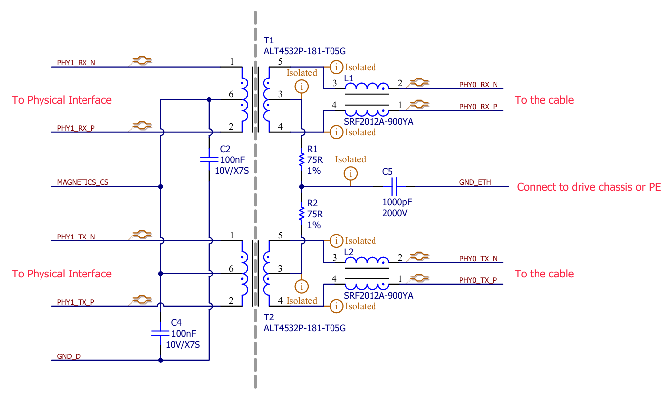
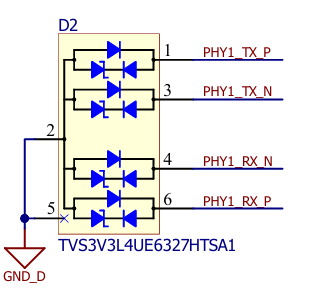
As in the previous circuit, protection against ESD and surge events is provided by external protection components connected to the differential signal pairs leading to the corresponding EtherCAT port of the drive.
|
|
Signals description
|
Signal |
Description |
EVE NET pins |
EVS/EVS-S/CAP NET pins |
DEN/DEN-S pins |
|---|---|---|---|---|
|
MAGNETICS_CS |
Center tap voltage of magnetics. |
Connect to pin 13 of the interface connector P4, a 3.3 V dedicated output. Do not connect this pin to another voltage source or load other than the center tap of the EtherCAT transformers. Do not connect to pin 14. |
Connect to pin 13 of the interface connector P4, a 1.8 V dedicated output. Do not connect this pin to another voltage source or load other than the center tap of the EtherCAT transformers. Do not connect to pin 14 |
Connect to the same voltage level as the pin 54 of the interface connector P2. Two voltages can be provided:
|
|
PHY0_TX_P |
EtherCAT differential pairs. These signals shall be connected to the drive side. Depending on whether the connection corresponds to the EtherCAT input port or output port, the assigned pins differ. |
Input port (port 0): pins 71, 73, 75 and 77 of the interface connector P4. Output port (port 1): pins 72, 74, 76 and 78 of the interface connector P4. |
Input port (port 0): pins 71, 73, 75 and 77 of the interface connector P4. Output port (port 1): pins 72, 74, 76 and 78 of the interface connector P4. |
Input port (port 0): pins 51, 53, 55 and 57 of the interface connector P2. Output port (port 1): pins 3, 5, 7 and 9 of the interface connector P2. |
|
PHY0_TX_N |
||||
|
PHY0_RX_P |
||||
|
PHY0_RX_N |
||||
|
PHY1_TX_P |
||||
|
PHY1_TX_N |
||||
|
PHY1_RX_P |
||||
|
PHY1_RX_N |
||||
|
\ETH0_LED_LINK |
Ethernet Port 0 Link signaling. |
Pins 67 of the interface connector P4. |
Pins 67 of the interface connector P4. |
Pins 49 of the interface connector P2. |
|
\ETH1_LED_LINK |
Ethernet Port 1 Link signaling. |
Pins 68 of the interface connector P4. |
Pins 68 of the interface connector P4. |
Pins 11 of the interface connector P2. |
|
GND_ETH |
Reference connection for the Ethernet differential pairs. This signal shall be connected to the reference of the Ethernet communication channel external to the interface board. In most applications, it corresponds to Protective Earth (PE) or the drive chassis connection. |
- |
- |
- |
|
GND_D |
Logic supply reference voltage. |
When the connected port is 0, use pins 69 and 79 of the interface connector P4. When the connected port is 1, use pins 70 and 80 of the interface connector P4. |
When the connected port is 0, use pins 69 and 79 of the interface connector P4. When the connected port is 1, use pins 70 and 80 of the interface connector P4. |
When the connected port is 0, use pin 59 of the interface connector P2. When the connected port is 1, use pin 1 of the interface connector P2. |
Design Notes
-
The center-tap voltage must be managed by the drive when using EVE, EVS, EVS-S, or CAP NET products. Follow the connection guidelines specified in the table above.
-
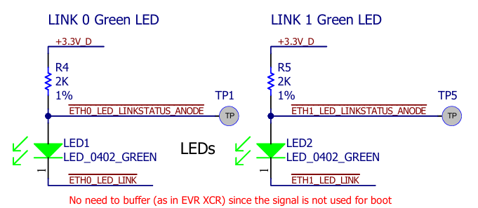
During drive startup, the corresponding \ETHX_LED_LINK act as configuration inputs and must remain high impedance, so a pull-up resistance must be placed to configure the magnetic coupling. Therefore, LEDs can be driven through an inverting buffer or connected directly like the above showed exemplification in the sinking current. than connected directly; otherwise, the Ethernet PHY may not operate correctly. More information can be encountered here.
-
LEDs could be driven from +3.3 V instead of +5 V to simplify logic supply. However this would entail a way less stable control of the LEDs brightness.
-
Although TVS do not affect the basic functionality of the Ethernet physical layer, it is not recommended to remove this protection, as it is mandatory to comply with the standard.
-
CHASSIS may not be connected to PE (Protective Earth), as the best way to connect the CHASSIS highly depends on the electrical scenario the system will be working into.
Bill of materials
|
Designator |
Part Number |
Manufacturer |
Package |
Value / Description |
|---|---|---|---|---|
|
C2, C4 |
C0603X7S1A104K030BC |
TDK Corporation |
0201 |
Ceramic capacitor, 100 nF, 10 V, X7S |
|
C5 |
1206Y2K00102KST |
Knowles Syfer |
1206 |
Ceramic capacitor, 1000 pF, 2000 V, X7R |
|
R1, R2 |
ERJ-2RKF75R0X |
Panasonic |
0402 |
75 Ω, 1% tolerance, 1/16W |
|
R4, R5 |
AC0201FR-072KL |
Yageo |
0201 |
2 ΩK, 1% tolerance, 1/20W |
|
L1, L2 |
SRF2012A-900YA |
Bourns |
0805 |
2 Line 2 Line Common Mode Choke, 125ºC, 90 Ω 50V @100MHz 370mA, DCR 300 mΩ |
|
T1, T2 |
ALT4532P-181-T05G |
TDK Corporation |
SMD 4.50mm x 3.20mm |
SMD LAN Transformer 180 µH 1CT:1CT |
|
D2 |
TVS3V3L4UE6327HTSA1 |
Infineon |
SC-74-6, SOT-457 |
Bi/uni-directional Zener TVS, 3.3V, 20A, 2pF |
|
LED1, LED2 |
APHHS1005CGCK |
Kingbright |
0402 |
Green LED |
Ethernet via RJ-45 (Magnetic Coupling)
This circuit includes the required electronics and protections required to set an Ethernet physical layer according to 100BASE-T standards.
Schematic
The main component is a dual RJ-45 connector with included magnetics. Decouplings and terminations to transformers center tap is included inside its housing.
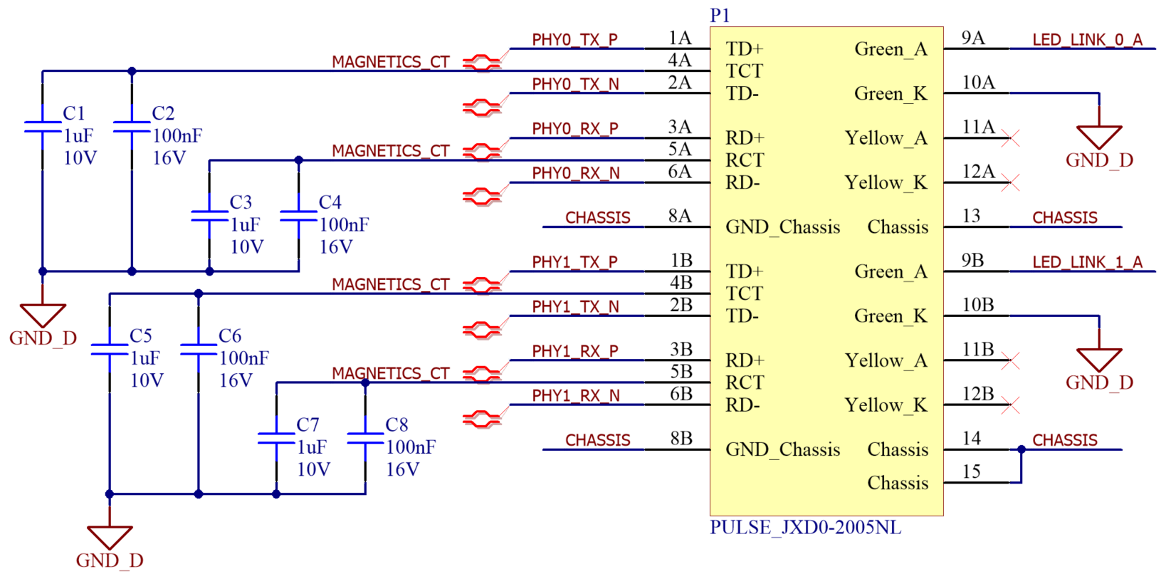
Additionally, specialized TVS provide protection in front of an ESD or surge event, the chassis of the RJ-45 connector (shorted to PE) is decoupled to GND for safety and LEDs also integrated in the RJ-45 housing are driven from drive.
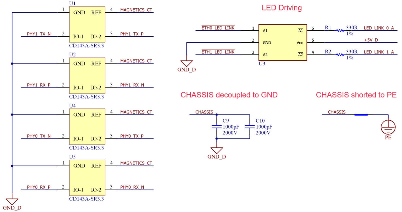
Link LED signals
Never drive an LED directly from \ETH0_LED_LINK or \ETH1_LED_LINK signals. For products EVE/EVS/EVS-S/CAP, always use an inverting buffer. See Design Notes below.
Signals description
|
Signal |
Description |
EVE NET pins |
EVS/EVS-S/CAP NET pins |
DEN/DEN-S pins |
|---|---|---|---|---|
|
+5V_D |
+5 V Logic supply |
- |
- |
- |
|
MAGNETICS_CT |
Center tap voltage of magnetics. |
Connect to pin 13 of the interface connector P4, a 3.3 V dedicated output. Do not connect this pin to another voltage source or load other than the center tap of the EtherCAT transformers. Do not connect to pin 14. |
Connect to pin 13 of the interface connector P4, a 1.8 V dedicated output. Do not connect this pin to another voltage source or load other than the center tap of the EtherCAT transformers. Do not connect to pin 14 |
Connect to the same voltage level as the pin 54 of the interface connector P2. Two voltages can be provided:
|
|
PHY0_TX_P |
EtherCAT differential pairs. |
Input port (port 0): pins 71, 73, 75 and 77 of the interface connector P4. Output port (port 1): pins 72, 74, 76 and 78 of the interface connector P4. |
Input port (port 0): pins 71, 73, 75 and 77 of the interface connector P4. Output port (port 1): pins 72, 74, 76 and 78 of the interface connector P4. |
Input port (port 0): pins 51, 53, 55 and 57 of the interface connector P2. Output port (port 1): pins 3, 5, 7 and 9 of the interface connector P2. |
|
PHY0_TX_N |
||||
|
PHY0_RX_P |
||||
|
PHY0_RX_N |
||||
|
PHY1_TX_P |
||||
|
PHY1_TX_N |
||||
|
PHY1_RX_P |
||||
|
PHY1_RX_N |
||||
|
\ETH0_LED_LINK |
Ethernet Port 0 Link LED signaling. Must be buffered and inverted to drive a LED |
Pins 67 of the interface connector P4. |
Pins 67 of the interface connector P4. |
Pins 49 of the interface connector P2. |
|
LED_LINK_0_A |
Anode of green LED integrated in Port 0 of the RJ-45 connector |
- |
- |
- |
|
\ETH1_LED_LINK |
Ethernet Port 0 Link LED signaling. Must be buffered and inverted to drive a LED |
Pins 68 of the interface connector P4. |
Pins 68 of the interface connector P4. |
Pins 11 of the interface connector P2. |
|
LED_LINK_1_A |
Anode of green LED integrated in Port 1 of the RJ-45 connector |
- |
- |
- |
|
CHASSIS |
Metallic case of the RJ-45 connector |
- |
- |
- |
|
PE |
Protective Earth |
- |
- |
- |
|
GND_D |
Logic supply reference voltage. |
When the connected port is 0, use pins 69 and 79 of the interface connector P4. When the connected port is 1, use pins 70 and 80 of the interface connector P4. |
When the connected port is 0, use pins 69 and 79 of the interface connector P4. When the connected port is 1, use pins 70 and 80 of the interface connector P4. |
When the connected port is 0, use pin 59 of the interface connector P2. When the connected port is 1, use pin 1 of the interface connector P2. |
Design Notes
-
The center-tap voltage must be managed by the drive when using EVE, EVS, EVS-S, or CAP NET products. Follow the connection guidelines specified in the table above.
-
Signals \ETH0_LED_LINK and \ETH1_LED_LINK behave as configuration inputs during boot up of drive. For products EVE/EVS/EVS-S/CAP, this signals must always be connected to a high impedance, which means they should never drive an LED directly, but by means of an inverting buffer (U3). If this advice is not respected, the Ethernet physical layer could not work at all.
-
LEDs could be driven from +3.3 V instead of +5 V to simplify logic supply. However this would entail a way less stable control of the LEDs brightness.
-
Although TVS do not affect the basic functionality of the Ethernet physical layer, it is not recommended to remove this protection, as it is mandatory to comply with the standard.
-
CHASSIS may not be connected to PE (Protective Earth), as the best way to connect the CHASSIS highly depends on the electrical scenario the system will be working into.
Bill of materials
|
Designator |
Part Number |
Manufacturer |
Package |
Value / Description |
|---|---|---|---|---|
|
C1, C3, C5, C7 |
C1005X7S1A105K050BC |
TDK |
0402 |
Ceramic capacitor, 1 µF, 10 V, X7S |
|
C2, C4, C6, C8 |
GRM155R71C104KA88D |
Murata |
0402 |
Ceramic capacitor, 100 nF, 16 V, X7R |
|
C9, C10 |
1206GC102KAT1A |
AVX |
1206 |
Ceramic capacitor, 1 nF, 2000 V, X7R |
|
P1 |
JXD0-2005NL |
Pulse |
RJ45 8p8c |
Dual RJ45 connector with magnetics, shielded, yellow and green LEDs included |
|
R1, R2 |
RMCF0603FT330R |
Stackpole |
0603 |
Thick film resistor, 330 Ω, 1 % tolerance, 0.1 W |
|
U1, U2, U4, U5 |
CD143A-SR3.3 |
Bourns |
SOT143 |
Steering / TVS diode array, 3.3 V standoff, Ethernet application-specific |
|
U3 |
NL27WZ14DFT2G |
ON Semiconductor |
SC88 / SC70-6 |
Dual Schmitt trigger inverting buffer, 24 mA output, 1.65 V to 5.5 V supply |
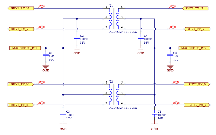
EtherCAT / Ethernet connection between 2 drives on the same PCB (Magnetic Coupling)
When 2 drives are mounted on the same board, many of the components needed for EtherCAT can be simplified to save space and cost. Note that there is no need for RJ45 connectors, ESD protections or high voltage capacitors.
The following schematic shows the minimal components on a board connection. Moreover, make sure that the respective \ETHX_LED_LINK of the port participating in the magnetic link is pulled-up. More information can be found here.
Note that EVE-NET does not support capacitive coupling by default. It is therefore not recommended.
Bill of materials
|
Designator |
Part Number |
Manufacturer |
Value / Description |
|---|---|---|---|
|
C1, C6 |
C1005X7S1A105K050BC |
TDK |
Ceramic capacitor, 1 µF, 10 V, X7S |
|
C2, C3, C4, C5 |
GRM155R71C104KA88D |
Murata |
Ceramic capacitor, 100 nF, 16 V, X7R |
|
T1, T2 |
ALT4532P-181-T05G |
TDK Corporation |
SMD LAN Transformer 180 µH 1CT:1CT |
EtherCAT / Ethernet connection between 2 drives on the same PCB (Capacitive Coupling)
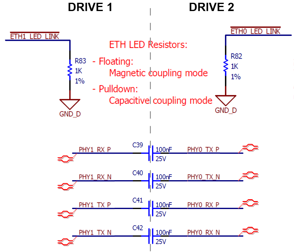
When two EVS/EVS-S/CAP/DEN/DEN-S NET drives are mounted on the same PCB, a transformerless Ethernet connection can be implemented using capacitive coupling. Ensure that the corresponding \ETHX_LED_LINK signal of the port participating in the capacitive link is pulled-down. Further details can be found here.
Auto-negotiation between Ethernet ports is supported only when magnetic coupling is used and is not available with capacitive coupling. For capacitive-coupled interfaces, the transmit pair (TX) of one port shall be connected to the receive pair (RX) of the opposite port, and vice versa, to ensure proper communication.
Bill of materials
|
Designator |
Part Number |
Manufacturer |
Value / Description |
|---|---|---|---|
|
C39, C40, C41, C42 |
CL05B104KA5NNNC |
Samsung Electro-Mechanics |
Ceramic capacitor, 100 nF, 25 V, X7R |
|
R82, R83 |
ERJ-2RKF1001X |
Panasonic Electronic Components |
1 kΩ, 1% tolerance, 1/16W |
CAN (physical layer for CANopen)
Safe drives (EVS-S-NET and DEN-S-NET) do not have a CANOpen communication protocol available.
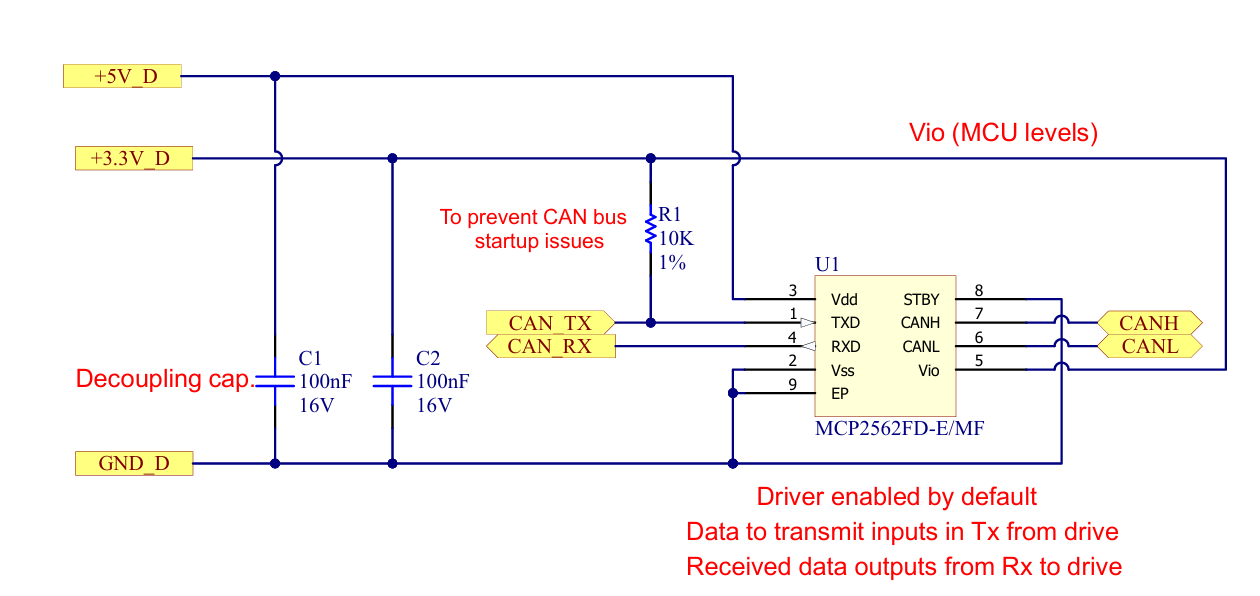
This transceiver will convert the differential levels of the CAN bus physical layer into 3.3 V levels.
Schematic
Signals description
|
Signal |
Description |
EVE/EVS/CAP NET |
DEN NET pins |
|---|---|---|---|
|
+3.3V_D |
+3.3 V Logic supply |
- |
- |
|
CAN_P |
Positive terminal of CAN bus (CAN High) |
- |
- |
|
CAN_N |
Negative terminal of CAN bus (CAN Low) |
- |
- |
|
CAN_RX |
To be connected to the Interface connector. |
Pins 57 of the interface connector P4. |
Pins 21 of the interface connector P2. |
|
CAN_TX |
To be connected to the Interface connector. |
Pins 55 of the interface connector P4. |
Pins 19 of the interface connector P2. |
|
GND_D |
Logic supply reference voltage. |
Pins 59 of the interface connector P4. |
Pins 31 of the interface connector P2. |
Design Notes
-
The VIO pin allows the CAN transceiver to interface directly with a 3.3 V MCU by setting the logic levels of the digital I/O pins. It does not affect the voltage levels of the CANH and CANL bus signals.
-
Resistor R1 is required by the drive during boot-up self-configuration.
-
C1 and C2 are decoupling capacitors for U1.
-
A 120 Ω termination resistor shall be installed only at the two end nodes of the CAN bus (CANH and CANL), including the master node when it is located at one end of the network.
Bill of materials
|
Designator |
Part Number |
Manufacturer |
Package |
Value / Description |
|---|---|---|---|---|
|
C1, C2 |
GRM155R71C104KA88D |
Murata |
0402 |
Ceramic capacitor, 100 nF, 16 V, X7R |
|
R1 |
RMCF0402FT10K0 |
Stackpole |
0402 |
Thick film resistor, 10 kΩ, 1 % tolerance, 1/16 W |
|
U1 |
SN65HVD234DR |
Texas Instruments |
8-SOIC |
CAN transceiver, 1 Mbps |
Feedbacks
Digital Halls
This circuit assume a typical open collector output from a digital hall circuitry and provides 5 V level pull-ups to interface it. Then, a 1st order RC filter plus an Schmitt trigger buffer filter the signal and translates it to 3.3 V levels for a decent ruggedness against noise.
Schematic
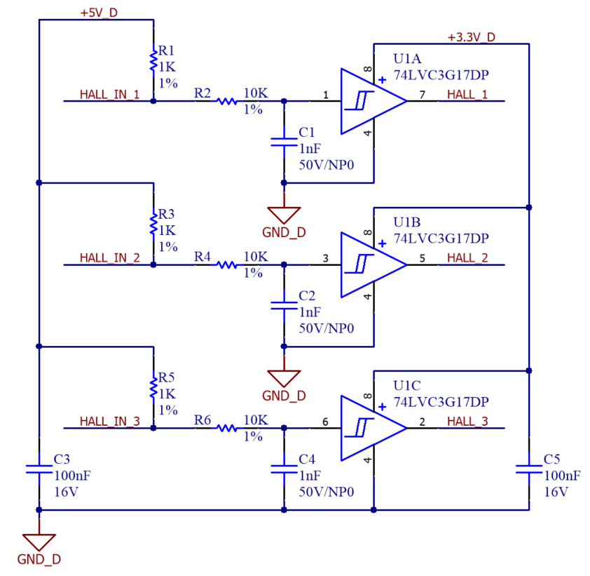
Signals description
|
Signal |
Description |
EVE/EVS/EVS-S/CAP pins |
DEN/DEN-S pins |
|---|---|---|---|
|
+3.3V_D |
+3.3 V Logic supply |
- |
- |
|
+5V_D |
+5 V Logic supply |
- |
- |
|
HALL_IN_1 |
Digital hall inputs from motor |
- |
- |
|
HALL_IN_2 |
|||
|
HALL_IN_3 |
|||
|
HALL_1 |
To be connected to the drive side respective pins. |
Pin 17 of connector P3. |
Pin 48 of connector P2. |
|
HALL_2 |
Pin 19 of connector P3. |
Pin 50 of connector P2. |
|
|
HALL_3 |
Pin 21 of connector P3. |
Pin 52 of connector P2. |
|
|
GND_D |
Logic supply reference voltage. |
Pin 15 of connector P3. |
Pin 36 of connector P2. |
Design Notes
-
U1 is represented as 3 symbols, A, B and C, but still a single component.
-
The RC filter makes a 1st order fc(-3dB) ≈ 16 kHz, but having the bandwidth of U1, the circuit should work fine with signals up to 5 kHz.
-
C5 is decoupling capacitor for U1.
-
U1 alone might have sufficient ESD protection.
Bill of materials
|
Designator |
Part Number |
Manufacturer |
Package |
Value / Description |
|---|---|---|---|---|
|
C1, C2, C4 |
C1005NP01H102J050BA |
TDK |
0402 |
Ceramic capacitor, 1 nF, 50 V, NP0 (but not necessarily have to be NP0 capacitors) |
|
C3, C5 |
GRM155R71C104KA88D |
Murata |
0402 |
Ceramic capacitor, 100 nF, 16 V, X7R |
|
R1, R3, R5 |
RMCF0402FT1K00 |
Stackpole |
0402 |
Thick film resistor, 1 kΩ, 1 % tolerance, 1/16 W |
|
R2, R4, R6 |
RMCF0402FT10K0 |
Stackpole |
0402 |
Thick film resistor, 10 kΩ, 1 % tolerance, 1/16 W |
|
U1 |
74LVC3G17DP,125 |
NXP |
8-TSSOP |
Non-inverting triple Schmitt trigger buffer, 24 mA output, 1.65 V to 5.5 V supply |
Differential Quadrature / Incremental Encoder
Since the inputs of the drive are single ended 3.3 V level, signal receivers or adapters may be needed to convert differential encoder lines to single ended, filter them against noise or provide terminations or fail-safe pull-up or pull-downs.
The following circuit RS422/RS485 line receivers as hysteresis comparators. Line receivers perform very good in this kind of circuits due to its its price, high speed response, common mode tolerance and built-in ESD protection. The negative terminal is biased to 2.5 V for compatibility with single-ended encoders, while the positive terminal is pulled-up for an extra robustness in front of a weak and noisy connection.
Schematic
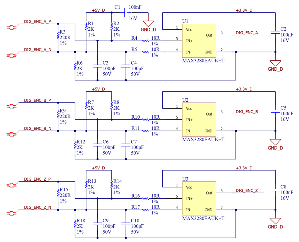
Signals description
|
Signal |
Description |
EVE/EVS/EVS-S/CAP |
DEN/DEN-S pins |
|---|---|---|---|
|
+3.3V_D |
+3.3 V Logic supply |
- |
- |
|
+5V_D |
+5 V Logic supply |
- |
- |
|
DIG_ENC_A |
To be connected to the respective Incremental Encoder 1 or/and Incremental Encoder 2. |
Incremental Encoder 1: pin 24, 26 and 28 of connector P3. Incremental Encoder 2: pin 30, 32 and 34 of connector P3. |
Incremental Encoder 1: pin 42, 44 and 46 of connector P2.
|
|
DIG_ENC_B |
|||
|
DIG_ENC_Z |
|||
|
DIG_ENC_A_P |
Incremental encoder channel A differential pair |
- |
- |
|
DIG_ENC_A_N |
|||
|
DIG_ENC_B_P |
Incremental encoder channel B differential pair |
- |
- |
|
DIG_ENC_B_N |
|||
|
DIG_ENC_Z_P |
Incremental encoder Index differential pair |
- |
- |
|
DIG_ENC_Z_N |
|||
|
GND_D |
Logic supply reference voltage. |
Whenever Incremental Encoder 1 is wired: pin 22 of connector P3. Whenever Incremental Encoder 2 is wired: pin 36 of connector P3. |
Pin 36 of connector P2. |
Design Notes
-
Resistors R3, R9 and R15 are termination resistors of a suggested 220 Ω value. Note that although 120 Ω is the recommended value for the best signal to noise-ratio on differential lines, a 120 Ω resistor tend to create unnecessary power consumption of the encoders (heating them up) and in most cases it is simply not necessary, a 220 Ω termination has empirically proven to work well for most encoders and wirings. If extra power saving was needed, consider also RC AC termination.
-
C3, C4, C6, C7, C9 and C10, in combination with R4, R5, R10, R11, R16 and R17, perform a protective function of the transceiver in front of spikes or ESD, and at the same time increases immunity to common mode noise. Capacitors could be increased up to 220 pF to reinforce this effects even more if required.
-
C2, C5 and C8 are decoupling capacitors for U1, U2 and U3.
-
To interface a single-ended encoder, connect the ABZ signals to the positive terminal of each differential pair and leave the negative unconnected. It is mandatory that the encoder and the drive then share their reference voltage or Ground.
Bill of materials
|
Designator |
Part Number |
Manufacturer |
Package |
Value / Description |
|---|---|---|---|---|
|
C1, C2, C5, C8 |
GRM155R71C104KA88D |
Murata |
0402 |
Ceramic capacitor, 100 nF, 16 V, X7R |
|
C3, C4, C6, C7, C9, C10 |
CC0402JRNPO9BN101 |
Yageo |
0402 |
Ceramic capacitor, 100 pF, 50 V, NP0 |
|
R1, R2, R6, R7, R8, R12, R13, R14, R18 |
RMCF0402FT2K00 |
Stackpole |
0402 |
Thick film resistor, 2 kΩ, 1 % tolerance, 1/16 W |
|
R3, R9, R15 |
ERJ3EKF2200V |
Panasonic |
0603 |
Thick film resistor, 220 Ω, 1 % tolerance, 0.1 W |
|
R4, R5, R10, R11, R16, R17 |
MC 0.063W 0603 1% 10R |
Multicomp |
0603 |
Thick film resistor, 10 Ω, 1 % tolerance, 1/16 W |
|
U1, U2, U3 |
MAX3280EAUK+T |
Maxim |
SOT-23-5N |
Single differential RS422/RS485 line receiver, 52 Mbps, 3 V to 5.5 V supply |
Absolute Encoder
This circuit is designed to set a RS422/485-based physical layer, which is the most common among absolute encoders. It sets 2 half-duplex channels, one for the "clock" signal, which is always a transmitter driven from the drive, and the other for the "data" signal, which is always a receiver. With this, EVE/EVS/CAP/DEN will be able to interface most SSI or BISS-C absolute encoders available.
Schematic
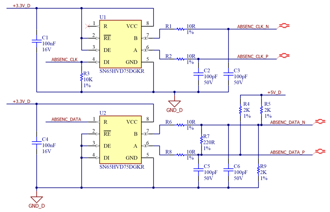
Signals description
|
Signal |
Description |
EVE/CAP CORE pins |
EVE/EVS/EVS-S/CAP NET pins |
DEN/DEN-S NET pins |
|---|---|---|---|---|
|
+3.3V_D |
+3.3 V Logic supply |
- |
- |
- |
|
+5V_D |
+5 V Logic supply |
- |
- |
- |
|
ABSENC_CLK_N |
Clock output differential pair to absolute encoder |
- |
- |
- |
|
ABSENC_CLK_P |
- |
- |
- |
|
|
ABSENC_DATA_N |
Data input differential pair to absolute encoder |
- |
- |
- |
|
ABSENC_DATA_P |
- |
- |
- |
|
|
ABSENC_CLK |
Clock signal from the drive. |
Absolute Encoder 1: pins 38 and 40 of connector P3. Absolute Encoder 2: pins 50 and 51 of connector P4. |
Absolute Encoder 1: pins 38 and 40 of connector P3. Absolute Encoder 2: pins 24 and 25 of connector P4. |
Absolute Encoder 1: pins 34 and 32 of connector P2. Absolute Encoder 2: pins 38 and 40 of connector P2. |
|
ABSENC_DATA |
Data signal from the drive |
|||
|
GND_D |
Logic supply reference voltage. |
Whenever Absolute Encoder 1 is wired: pin 36 or 44 of connector P3. Whenever Absolute Encoder 2 is wired: pin 59 or 60 of connector P4. |
Whenever Absolute Encoder 1 is wired: pin 36 or 44 of connector P3. Whenever Absolute Encoder 2 is wired: pin 16 or 35 of connector P4. |
Whenever Absolute Encoder 1 is wired: pin 31 or 36 of connector P2. Whenever Absolute Encoder 2 is wired: pin 36 of connector P2. |
Design Notes
-
The circuit does not include a termination resistor the Clock output, although it might be advisable if the absolute encoder is connected along a very long cable (> 3 m), or a harsh electromagnetic environment.
-
R7 is the termination resistor for the data input. In the schematic a 220 Ω resistor is suggested. Note that although 120 Ω is the recommended value for the best signal to noise-ratio on differential lines, a 120 Ω resistor tend to create unnecessary power consumption of the encoders (heating them up) and in most cases it is simply not necessary, a 220 Ω termination has empirically proven to work well for most encoders and wirings. If extra power saving was needed, consider also RC AC termination.
-
C2, C3, C5 and C6, in combination with R1, R2, R6 and R8, perform a protective function of the transceiver in front of spikes or ESD, and at the same time increases immunity to common mode noise. Capacitors could be increased up to 220 pF to reinforce this effects even more if required.
-
If a stronger ESD protection is required, a TVS diodes with capacitance <100 pF are acceptable, whenever C2, C3, C5 and C6 values are kept as suggested.
-
The Data receiver uses a resistor voltage divider to set a 2.5 V bias. This would allow connecting this circuit to a single-ended absolute encoder and still being able to read it properly. In this case, leave the negative terminal of the differential pair unconnected.
-
R4 pulls-up the positive terminal for an extra robustness in front of a weak and noisy connection.
-
C1 and C4 are decoupling capacitors for U1 and U2.
Bill of materials
|
Designator |
Part Number |
Manufacturer |
Package |
Value / Description |
|---|---|---|---|---|
|
C1, C4 |
GRM155R71C104KA88D |
Murata |
0402 |
Ceramic capacitor, 100 nF, 16 V, X7R |
|
C2, C3, C5, C6 |
CC0402JRNPO9BN101 |
Yageo |
0402 |
Ceramic capacitor, 100 pF, 50 V, NP0 |
|
R1, R2, R6, R8 |
MC 0.063W 0603 1% 10R |
Multicomp |
0603 |
Thick film resistor, 10 Ω, 1 % tolerance, 1/16 W |
|
R3 |
RMCF0402FT10K0 |
Stackpole |
0402 |
Thick film resistor, 10 kΩ, 1 % tolerance, 1/16 W |
|
R7 |
ERJ3EKF2200V |
Panasonic |
0603 |
Thick film resistor, 220 Ω, 1 % tolerance, 0.1 W |
|
R4, R5, R9 |
RMCF0402FT2K00 |
Stackpole |
0402 |
Thick film resistor, 2 kΩ, 1 % tolerance, 1/16 W |
|
U1, U2 |
SN65HVD75DGKR |
Texas Instruments |
8-VSSOP |
RS485/422 half-duplex transceiver, 20 Mbps |
LED Signaling
All Sumit Series drives except CORE ones, allow directly driving small LEDs for signaling up to 3 mA. This circuits would provide signaling for EtherCAT / CANopen status signals and Fault signaling of the internal state-machine of the integrated drive.
Schematic
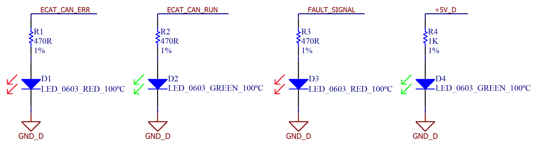
Signals description
|
Signal |
Description |
EVE/CAP CORE pins |
EVE/EVS/EVS-S/CAP NET pins |
DEN/DEN-S NET pins |
|---|---|---|---|---|
|
+5V_D |
+5 V Logic supply for power ON signaling |
- |
- |
- |
|
FAULT_SIGNAL |
Fault state of the motion controller signaling. |
Pins 37 of connector P4. |
Pins 36 of connector P4. |
Pins 43 of connector P2. |
|
ECAT_CAN_RUN |
EtherCAT / CANopen "Run" status signal. |
- |
Pins 65 of connector P4. |
Pins 45 of connector P2. |
|
ECAT_CAN_ERR |
EtherCAT / CANopen "Error" status signal. |
- |
Pins 64 of connector P4. |
Pins 47 of connector P2. |
|
GND_D |
Logic supply reference voltage. |
Pins 39 of connector P4. |
Pins 38, 60, 69 or 70 of connector P4. |
Pins 36, 59 or 60 of connector P2. |
Design Notes
-
In case brighter LEDs are required, non-inverting buffers or transistors can be used to increase the output current.
-
Also, brightness might substantially vary with this solution, as 3 of the 4 signals carry 3.3 V levels. Using level shifters to 5 V, and re-dimensioning resistors R1, R2 and R3 will notably improve brightness stability.
Bill of materials
|
Designator |
Part Number |
Manufacturer |
Package |
Value / Description |
|---|---|---|---|---|
|
R1, R2, R3 |
RC0402FR-07470RL |
Yageo |
0402 |
Thick film resistor, 470 Ω, 1 % tolerance, 1/16 W |
|
R4 |
RMCF0402FT1K00 |
Stackpole |
0402 |
Thick film resistor, 1 kΩ, 1 % tolerance, 1/16 W |
|
D1, D3 |
TLMS1100-GS08 |
Vishay |
0603 |
Red diode LED, 63 mcd, 100 ºC |
|
D2, D4 |
TLMG1100-GS08 |
Vishay |
0603 |
Green diode LED, 35 mcd, 100 ºC |
Motor Phases
It is recommended to install a motor choke as close to the drive as possible. By increasing the impedance at high frequencies while allowing the fundamental motor currents to pass with minimal attenuation, the choke helps reduce the phase-current di/dt and phase-voltage dV/dt generated by the drive. This contributes to lower conducted and radiated electromagnetic emissions and reduces electrical stress on the motor cable and windings.
Various motor-choke and common-mode choke solutions are available, including PCB-mounted and cable-mounted implementations. Chokes are manufactured using different core materials, with nanocrystalline ferrites often providing excellent high-frequency attenuation. Refer to the product manual for guidance on the recommended choke and ferrite types for the specific application.
Never pass the PE cable through the motor choke. This will magnetically couple the interference to earth amplifying it. Consult the following article about EMC best practices.
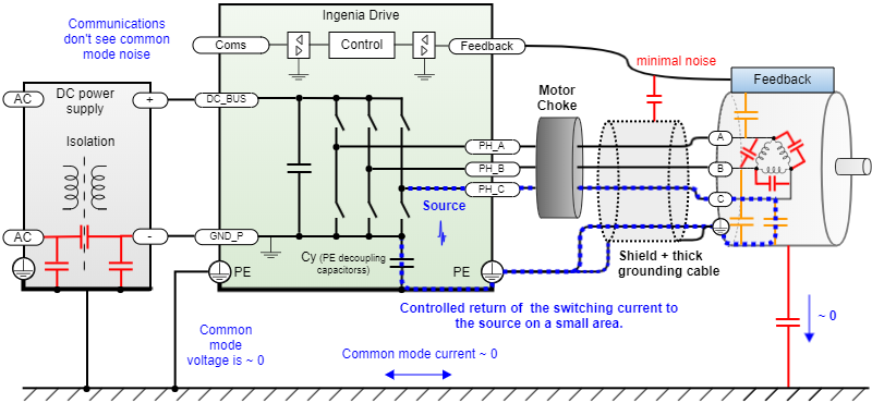
Grounding the motor chassis and providing a low-impedance connection, preferably through a short and robust PE conductor, between the motor chassis and the drive chassis or power ground is highly effective in reducing both conducted and radiated electromagnetic interference (EMI). This connection provides a localized return path for high-frequency currents, minimizing the current-loop area and consequently reducing electromagnetic emissions.
In applications where a direct connection between the motor chassis and the drive chassis or power ground is not possible, such as in isolated systems or where safety concerns are present, the connection may be established through an appropriately rated ceramic Y-capacitor. This approach, commonly implemented in motor drives, preserves galvanic isolation while still providing a low-impedance path for high-frequency common-mode currents, allowing high-frequency harmonic components to return to the drive power stage rather than propagating through the system.
When the motor and drive are mounted in close proximity, the mechanical structure itself may provide an adequate chassis connection, provided that a reliable and low-impedance electrical path exists between both assemblies. In such cases, a dedicated grounding conductor may not be required. However, mechanical joints, fasteners, bearings, or moving elements can introduce significant impedance. Therefore, the continuity and impedance of the return path should be carefully evaluated to ensure effective EMI mitigation.
|
Signal |
Description |
EVE/EVS/EVS-S/CAP pins |
DEN/DEN-S pins |
|---|---|---|---|
|
Phase A |
Motor phase A for 3-phase motors, positive for DC motors. |
The power pin 1 of P2. |
The power pin 3 of P1. |
|
Phase B |
Motor phase B for 3-phase motors, positive for DC motors.supply input |
The power pin 2 of P2. |
The power pin 4 of P1. |
|
Phase C |
Motor phase C for 3-phase motors, positive for DC motors.
|
The power pin 3 of P3. |
The power pin 5 of P1. |
|
PE |
Protective Earth. Could be left unconnected in specific cases |
To be connected to the chassis and fixing the respective threads. |
The product does not include a chassis as part of the delivered assembly. If an external chassis is incorporated into the final system, the protective earth connection shall be bonded to the chassis. |
|
GND_P |
Internal V_BUS reference voltage. |
The power pin 2 of P1 |
The power pin 1 of P1. |