
Concept and Specifications
Concept
For decades, industrial robots have been built under the same widespread approach by which the robot body contains only mechanics, motors, and sensors, while the control electronics, including the servo drives, are located inside a separate cabinet. This strategy is quite convenient to remove a traditionally bulky component, the drive containing the power electronics, from the space-constrained robot body, allowing it to be slimmer and lighter.
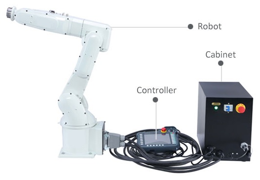
Undisputedly dominant distribution of an industrial robot’s parts.
However, this approach is now an oldie, and the source of uncountable wiring and EMC problems and limitations that have been undermining the evolution of these robots, preventing them from embedding components with greater power density, taking advantage of more efficient converters, or evolving towards modular constructive approaches.
Collaborative robots, by contrast, were already born with those goals in mind. But to get modular, more flexible, slimmer, and safer bodies, the drives must be attached to the robot joints, as close as possible to the motors and sensors. Also, the established use of electronically-commutated PMSMs instead of power steppers or AC motors made modern miniature servo drives highly convenient.
The term “miniature” servo drive is accurate here, given the fact that these robot joints require a whole new scale of integration. The component population is so dense that most collaborative robots cannot pipe the pneumatics or end-effector-specific wirings across its interior, and so those must be intricately disposed around the robot. Also, a rather flat or short form factor of the joints benefits the overall mobility of the cobot, but very often the electronics take 30 % of the total joint volume, or even more, making those longer than desired.
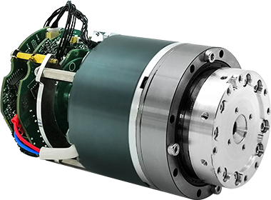
An integrated robot joint
Even so, the metal parts connecting each joint to the next one, also known as mechanical links, are basically underutilized empty tubes in the majority of collaborative robots in the market. These mechanical links are often used only to pass wires through, while all the complexity of integration is allocated in the robot joints.
The proposed design here is intended to pose an alternative to this common approach by using mechanical links to hold the power electronics. The strategy is not new, though, as it is widely used among surgical robots, which nowadays are at the forefront of robotic arm technology.
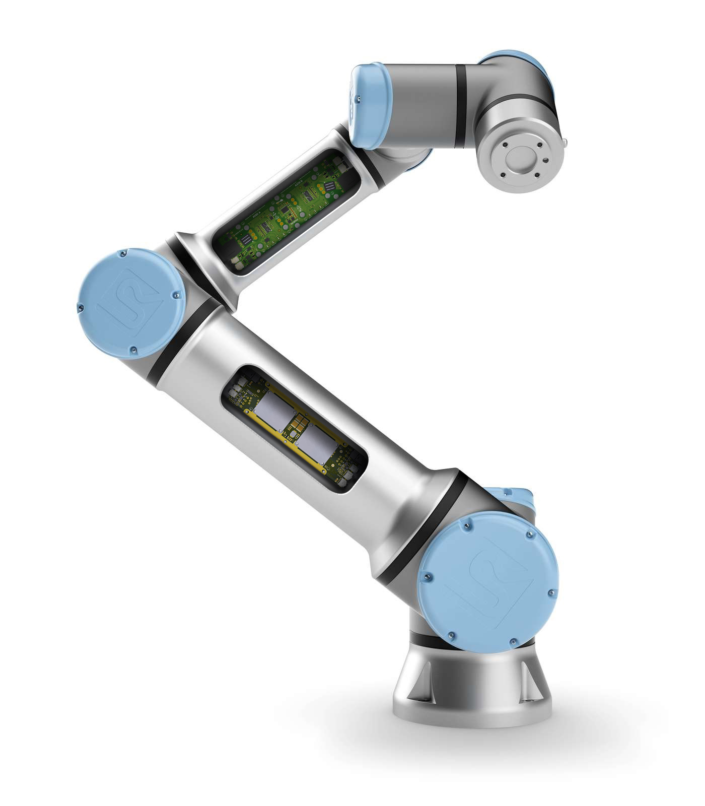
The proposed location of the drives inside a popular cobot (fictional).
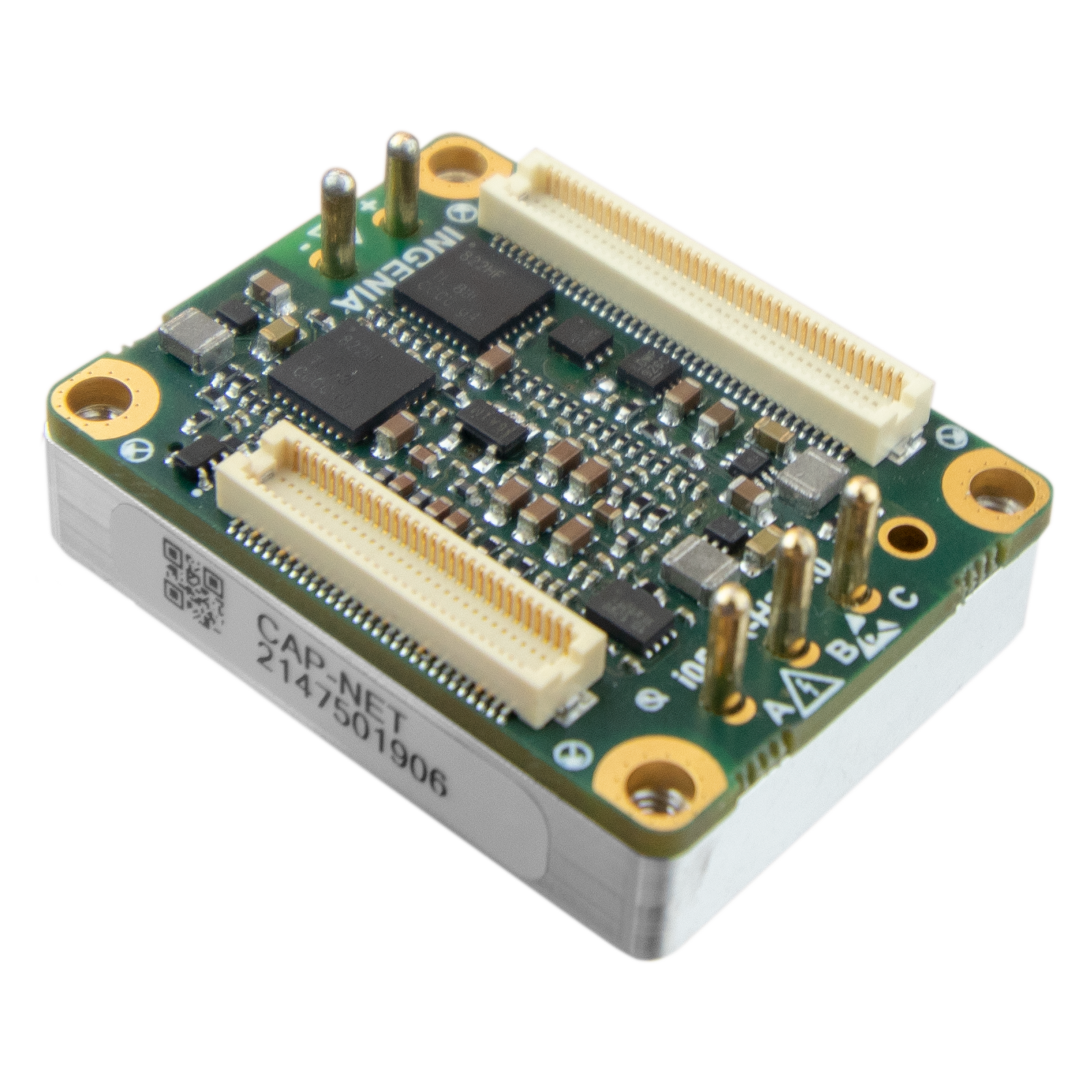
But unlike surgical robots, where each part is highly specialized and uniquely tailored to a particular robot, cobot manufacturers seek modularity, using a common range of joints and links to build larger and smaller robots. Where this modularity would typically entail the size of the servo drives to be adapted to the size of the joint for optimization, hence having to dedicate drives of different sizes and power ratings, this is not the case with the proposed design thanks to its main component, the Capitan NET miniature servo drive. With a power rating of 500 W in a footprint of only 34.5 mm x 26 mm, it can drive the bigger joints and still satisfy the space constraints of the smaller ones, enabling the same electronically-loaded mechanical link to be used in stronger and lighter robots.
Finally, although designed with collaborative robot arms in mind, this design example presents a powerful and versatile dual-axis servo drive that could be perfectly suited for many other applications.
Main advantages
Frees up space from the robot joints, typically the most space-constrained location in a cobot, yet is close enough to the motors and sensors to prevent eventual EMI issues.
Two 500 W advanced servo drives in a 140 mm x 38 mm footprint (excluding matings), can be embedded even a tube as narrow as Ø40 mm.
Power supply, STO, and EtherCAT daisy-chain connections embedded on-board: there is no need for aerial T-connections. Still, when embedded in a cylinder, leaves plenty of space to pass wires through the mechanical link.
Heat dissipation towards the largest and coldest metal parts of the robot.
The design can also be used in any other context requiring a dual-axis
Specifications
See the Mechanical Specifications section of this guide for further details on the physical characteristics of the design.
This design example requires 2x CAP-NET-E servo drives. Check the full set of specifications in the Capitan NET Product Manual.
The following characteristics are given as a reference only, and do not represent a binding depiction of the capacities of Capitan NET servo drive.
In case of mismatch, always rely only on the contents of the Capitan NET Product Manual.
Electrical Specifications
Minimum DC bus supply voltage | 8 VDC |
|---|---|
Maximum DC bus supply voltage | 60 VDC (continuous) |
Recommended power supply voltage range | 12 VDC ~ 48 VDC This voltage range ensures a safety margin including power supply tolerances and regulation during acceleration and braking. |
Internal drive DC bus capacitance | 67 µF Does not include Capitan’s internal capacity. Uses ceramic capacitors., hence the capacitance value varies with DC bias and temperature. |
Maximum continuous phase current | 10 A @ 48 V, 50 kHz, <85 ºC case temperature. Automatic current derating can limit the maximum allowable current when case temperature is >85 ºC. See Thermal and Power Specifications section of Capitan NET Product Manual for further detail. For disambiguation on current definitions please see Disambiguation on current values and naming for Ingenia Drives. |
Maximum peak phase current | 20 A @ 1 sec |
Maximum continuous output power | >500 W each Capitan NET How the output power is calculated in an Ingenia drive. |
Maximum DC Bus voltage utilization per available power stage PWM frequency | 99.5% @ 20 kHz 98.9% @ 50 kHz 97.95% @ 100 kHz 96% @ 200 kHz Assuming a Sinusoidal commutation and no load connected. |
Standby logic supply consumption | ≤1.3 W typ. See Standby power consumption section in Capitan NET Product Manual for further detail. |
Motion Control Specifications
Available communications | EtherCAT (CoE, FoE, and EoE supported) 100Base-T Ethernet physical layer. |
|---|---|
Supported target sources | Network (EtherCAT) |
Supported motor types |
|
Control modes |
|
Max. current loop frequency | 50 kHz Check the Power Stage & Control loops relationship section in Capitan NET Product Manual for further detail. |
Max. servo loops frequency (position, velocity & commutation) | 25 kHz Check the Power Stage & Control loops relationship section in Capitan NET Product Manual for further detail. |
Current sensing | 3 phase, shunt-based current sensing. 16 bit ADC resolution. Accuracy is ±2% full scale |
Current sense resolution | 1.007 mA/count |
Current sense ranges | ±33 A |
Feedbacks | 2x SSI or BiSS-C absolute encoders per drive. RS-422/485 levels differential interface, 10 Mbps max. clock frequency. |
Inputs/Outputs and Protections
Feedbacks supply output | 5 VDC, max. 1 A ±25% |
|---|---|
Safe Torque OFF inputs | 2x dedicated, isolated, 24 V STO digital inputs |
Motor temperature input | 1x dedicated, 5 V, 12-bit, single-ended analog input for measuring motor temperature. NTC, PTC, RTD, linear voltage sensors , silicon-based sensors and thermal switches are supported. |
Motor brake output | 1 A, 60 V, dedicated brake output. Open drain with re-circulation diode and over-current protection. |
Onboard LEDs | Per each drive:
See further details in the LEDs Signalling section of this guide. |
Protections |
|