
LEDs Signalling
Overview
Onboard LEDs can be used to retrieve information on each drive’s operational state. Even if the LEDs are hidden from sight in the final application, their inclusion still provides valuable visual help during the development stage and troubleshooting or debugging afterward.
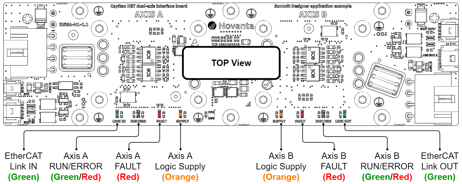
The following diagram represents the physical location of each LED on the TOP side of the proposed design:
LED | Type | Color | Description |
|---|---|---|---|
EtherCAT Link IN/OUT | Single | Green | EtherCAT input and output link LEDs:
|
Axis A/B RUN/ERROR | Bi-color | Green / Red | EtherCAT status (ECAT Status)
|
Axis A/B FAULT | Single | Red | Drive FAULT State (Drive status) LED is on when an error event has occurred and the drive is trapped in the Fault state. |
Axis A/B Logic Supply | Single | Orange | Drive’s +3.3 V internal supply (CAP-NET pin 14. Indicates the logic circuits of the drive are supplied. |
Find out more about the behavior of these signals along the whole range of Summit drives in the LED Signaling chapter of the Application Guide.