
LED Signaling
All the Summit drives output a series of signals that are primarily intended to control LEDs for signaling. These LEDs would not only provide utility during the normal operation of the drive, but result in a very useful resource during the development or debugging of the application.
LED signals mapping
All the following signals can be found among the pins of the Interface Connector of each product.
LED name | Signal name | |||
|---|---|---|---|---|
RUN | ECAT_CAN_RUN | Pin 65 | Pin 45 | - |
ERROR | ECAT_CAN_ERR | Pin 64 | Pin 47 | - |
Link 0 | \ETH0_LED_LINK | Pin 67 | Pin 49 | - |
Link 1 | \ETH1_LED_LINK | Pin 68: | Pin 11 | - |
Fault | FAULT_SIGNAL | Pin 36 | Pin 43 | Pin 37 |
LED activity definitions
LED activity | Description |
|---|---|
OFF | The LED is constantly inactive. |
Flickering | The LED flickering will have an On and Off sequence with a frequency of approximately 10 Hz: on for approximately 50 ms and off for approximately 50 ms. 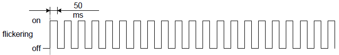 |
Blinking | The LED blinking will have an On and Off sequence with a frequency of approximately 2,5 Hz: On for approximately 200 ms followed by Off for approximately 200 ms. 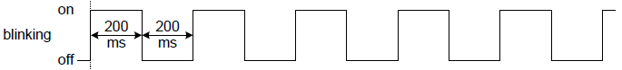 |
Single flash | The LED will have a short flash (approximately 200 ms) followed by a long off phase (approximately 1000 ms).  |
Double flash | The LED will have a sequence of two short flashes (approximately 200 ms), separated by an off phase (approximately 200 ms). The sequence is finished 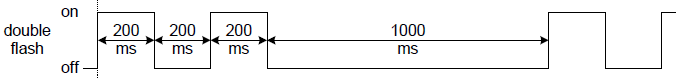 |
Triple flash | The LED will have a sequence of three short flashes (approximately 200 ms), separated by an off phase (approximately 200 ms). The sequence is finished 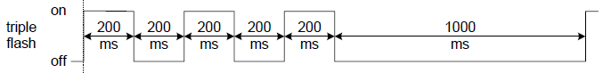 |
ON | The LED is constantly active. |
Network LED signals
The same RUN and ERROR LED signals behave differently and receive different meanings in EtherCAT-enabled drives and in CANopen-enabled ones. The Link LED signals, on the other hand, provide information about the activity of the Ethernet physical layer, which is common to EtherCAT and CANopen-enabled drives.
EtherCAT LED signals
The EtherCAT LEDs provide information regarding communication status according to the EtherCAT standard specification.
The RUN LED provides information about the EtherCAT network state machine, while the ERROR LED provides information about the EtherCAT communication status.
LED activity | RUN LED (green) | ERROR LED (red) |
|---|---|---|
OFF | EtherCAT slave status: INIT | EtherCAT slave status: No error |
Flickering | EtherCAT slave status: BOOTSTRAP | - |
Blinking | EtherCAT slave status: PRE-OPERATIONAL | EtherCAT slave status: Invalid configuration |
Single Flash | EtherCAT slave status: SAFE-OPERATIONAL | EtherCAT slave status: Local error |
Double Flash | - | EtherCAT slave status: Watchdog timeout |
ON | EtherCAT slave status: OPERATIONAL | - |
Startup behavior
Start-up signalling | RUN LED | ERROR LED |
|---|---|---|
Power ON The Slave drive will stay in the INIT state after power-up until the EtherCAT Master forces the transition to another state. | OFF | OFF |
FoE Bootloader After an EtherCAT Master state change. | OFF | Blinking |
CANopen LED signals
The CANopen LEDs provide information regarding communication status according to the recommendations of the CiA 303-3 standard.
The RUN LED indicates the status of the CANopen Slave state machine, while the ERROR LED indicates the status of the CAN network and errors due to missed CAN messages (sync, guard, or heartbeat).
LED activity | RUN LED (green) | ERROR LED (red) |
|---|---|---|
OFF | The drive is switched OFF | No error: the drive is in working condition. |
Blinking | The drive is in state PRE-OPERATIONAL | - |
Single Flash | The drive is in state STOPPED | Warning limit reached: at least one of the error counters of the CAN controller has reached or exceeded the warning level (too many error frames). |
Double Flash | - | Error control event: a guard event (NMT-slave or NMT-master) or a heartbeat event (heartbeat consumer) has occurred. |
Triple Flash | - | Sync error: the sync message has not been received within the configured communication cycle period time out. |
ON | The drive is in state OPERATIONAL | Bus OFF: the CAN controller is in “Bus OFF” state. |
Start-up behavior
Start-up signalling | RUN LED | ERROR LED | Diagram |
|---|---|---|---|
Power ON During initialisation LEDs are OFF. If the initialisation finishes with no errors, the ERROR LED will remain OFF, and the change to the PRE-OPERATIONAL state will be notified by blinking the RUN LED, as depicted. | OFF → Blinking | OFF → OFF | 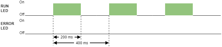 |
CAN Bootloader Starts in IDLE state. RUN and ERROR LEDs alternate ON-OFF at 5 Hz. A small green/red bi-color LED may be seen as orange. | Blinking | Blinking | 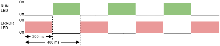 |
CAN Passive Error Would happen during start-up if a problem, like the CAN network disconnection, occurs during the transmission of the CAN boot-up message, a NMT message used to notify the presence of the Slave to the Master. The CAN Error state could also be reached after the start-up. | Blinking | Single flash | 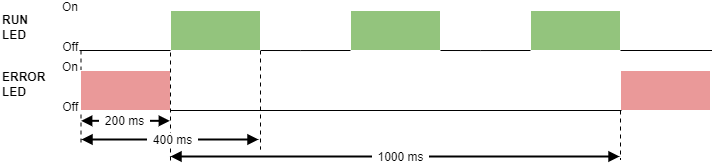 |
CAN Bus OFF A typical cause would be a short between CAN High and CAN Low lines. The CAN Bus OFF error state could also be reached after the start-up; in such case, the RUN LED signalling would depend on the previous state. | Blinking → Other | ON | 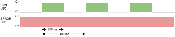 |
Link LED signals
The Link 0 and Link 1 LEDs provide information regarding the activity of Port 0 and Port 1 of the Ethernet physical layer, according to the IEEE 802.3 standard. Notice both EtherCAT and CANopen variants of the drive make use of the Ethernet network, hence both share the same signaling definition.
LED activity | LINK LEDs (typ. green/yellow) |
|---|---|
OFF | Port closed |
Flickering | Port opened (activity on port) |
ON | Port opened (no activity on port) |
While in Everest NET both Ethernet ports are available (they act as an Ethernet switch), in Everest S NET, Capitan NET, and Denali NET only Port 1 is enabled for Ethernet communications, hence only Link 1 LED will display activity. This does not apply to EtherCAT communications, where all the mentioned products have both Port 0 and Port 1 enabled.
Drive Status LED signals
LED activity | FAULT LED |
|---|---|
OFF | The drive operates normally (not in Fault state). |
ON | The drive is in Fault state * |
* See State Machine in the Operation section and Error Management section in the Reference Manual for further information.
Start-up behavior
Even if the drive finished the session in a Fault state, the LED will be OFF after the power cycle. If the Fault condition persists, the LED will turn ON when changing the state of the state machine.
Other LED signaling
Apart from the mentioned ones, some applications could benefit from using signals intended for other purposes than signaling to drive LEDs. When doing this, always make sure the LED is not overloading or delaying the source signal by using buffers, otherwise, the source signal could fail to accomplish its purpose. Also, when resolving the layout, add the buffer as close as possible to the source signal to prevent the extended track reaching it from becoming a noise antenna.
Some examples:
The internal 3.3V supply output would indicate the logic circuitry of that drive is supplied
Connecting a bright LED to the DC bus would make a safety indication that the power supply is active. If doing so, take care of limiting the LED current with safety margins, and select components with pad-to-pad clearances adequate to the maximum DC bus voltage to be expected.
GPO configured as a shunt braking resistor driver would serve as an overvoltage indicator.
GPO configured as “Health” can be used as an indicator that the drive is operating normally.
The PWM_BRAKE signal can also be used to indicate whether the load is free to move (may entail filtering the pulses and regenerating the logic signal by means of a Schmidt trigger buffer or comparator).
Limit switch signals can also indicate that the actuator is in the Homing position.
CAN_Tx and CAN_Rx can be used to display activity in the CAN bus.
The \MCB_SPI_CS can be used to display SPI activity in a specific CORE drive.
Stacking boards or panel mount
When the interface board must be covered by another PCB or mounted under an opaque surface, like the robot’s chassis or the machine’s box, LEDs can be made visible from the other side by means of light pipes. Those are small plastic optics intended to put the light of an LED a few millimeters away with minimum attenuation or interference from other light sources. See the following table for suggested parts.
 Manufacturer: Dialight Part Number: 515-1003F Length: 6 mm Lens size: 1 mm |  Manufacturer: Bivar Inc. Part Number: PLPC1-6MM Length: 6 mm Lens size: 1.3 mm | 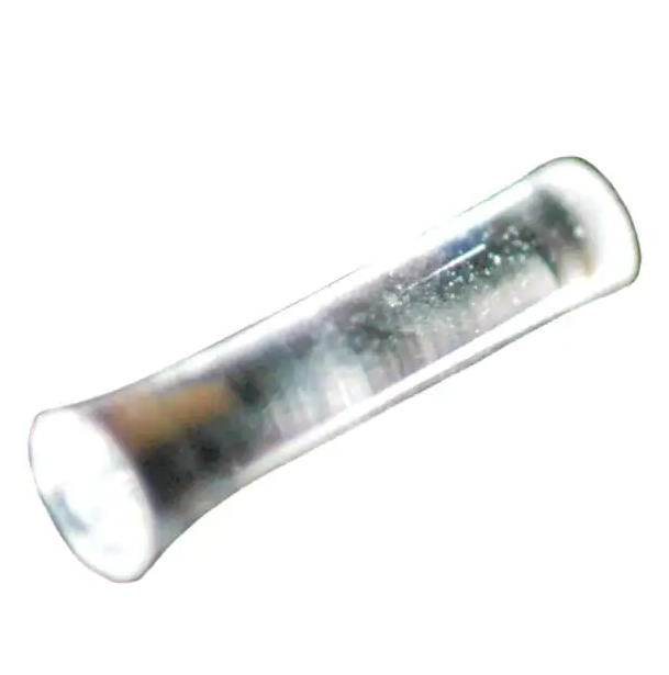 Manufacturer: Dialight Part Number: 515-1027F Length: 8.26 mm Lens size: 1.68 mm |  Manufactuer: Schurter Inc. Part Number: 3-102-195 Length: 32.7 mm Lens size: 2 mm |