
Mechanical Specifications
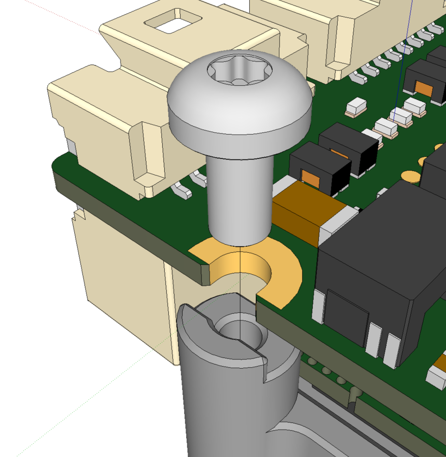
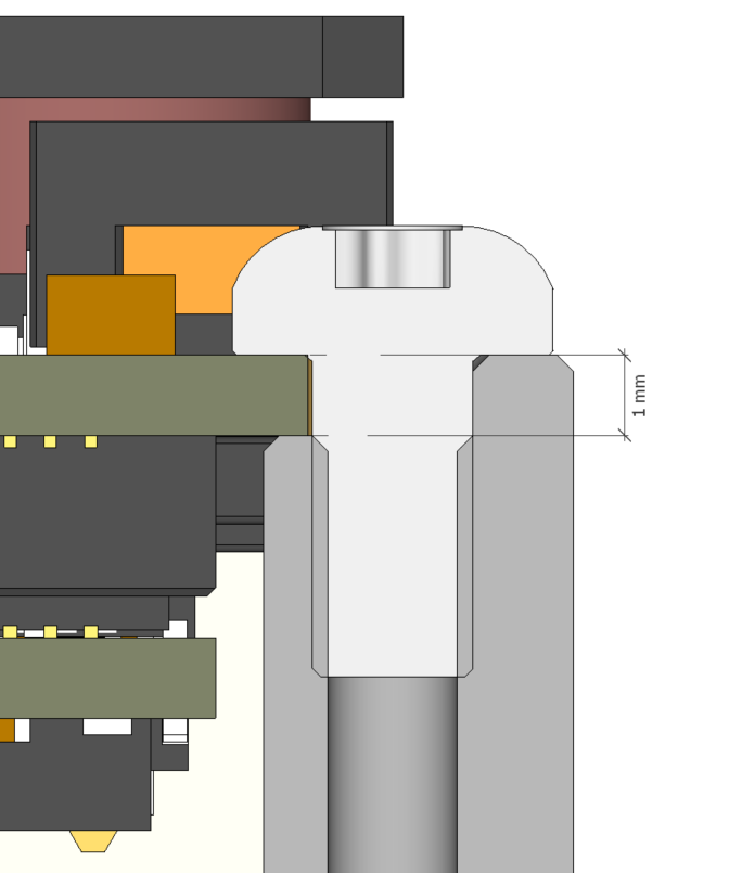
The drawings below show the actual dimensions of the design. The 4 open holes (M2 sized) shown are intended to fix the interface board to the support surface. The support element must be shaped in a 1 mm depth slot, matching the PCB thickness (as shown in the following images) to prevent the screws from tilting or pinching when fastened. The Denali NET underneath it is only fixed to the interface board by means of its connectors, so it is not attached to the support surface at all.
Along with the general dimensions of the interface board, find in the following drawing both the minimum recommended and absolute minimum distances to be respected from Denali NET to the support surface or any other element. Evaluating these distances is advised, as they have an impact on the overall product performance since the support surface will at the same time be used for heat dissipation:
Minimum distance:
Notice that getting the support surface closer helps reduce the thermal impedance of the gap, but getting too close may entail a risk of damaging the Denali NET due to electric arc or collision. As a general rule, no element should ever be closer to Denali NET than 0.5 mm. But as its surface is irregular, it is recommended to only use this minimum distance under the FET transistors (the main heat generators per unit of area), and leave at least 1 mm underneath the rest of the Denali NET.
Standoff height tolerance:
The “standoff height” is set by the mechanical element used to fix the interface board to the support/heatsink. These support elements can be given by single-piece precision-milled chassis, or by screw separators (hexagonal male-female standoffs or similar), which are typically manufactured under greater mechanical tolerances. Take this into account to avoid violating the said minimum dimensions.
Dissipating heat:
As the transistors will be the main heat generators when the Denali is driving high currents (which will typically happen transiently), the MCU will be the main heat generator in any other scenario. It also produces heat continuously, thus becoming by far the greatest heat generator when power losses are integrated over time. Hence, a proper dissipation of the MCU is crucial to achieve a low-temperature chassis in those applications where the robot surface is expected to be manually driven or in touch with the skin.
To properly perform, a thermal gap pad under the MCU or the transistors shall be compressed to approximately half of its thickness. This would typically happen when the interface board with the Denali already plugged will be screwed to the chassis or heatsink. At this point, excessive or uneven compression forces can bend either the Denali NET or the interface board, potentially damaging the smaller solderings or components. To prevent this, prefer thin gap pads (<2 mm) and compress carefully.
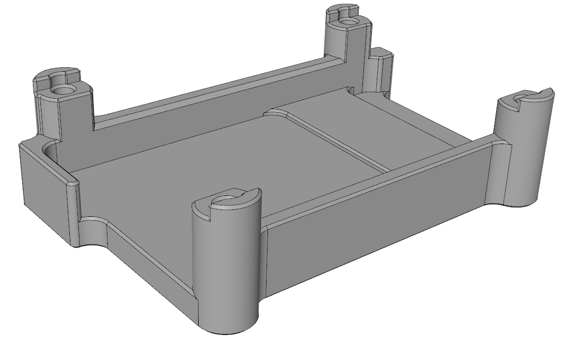
Notice the “compressed” thickness of the gap pad will determine the required standoff height. The following drawings represent a chassis profile that would work for most 1 mm gap pads under the transistors, and 1.5 mm (preferred) or 2 mm (max.) under the MCU area.
Learn more about Denali NET’s thermal model in its Product Manual.
See the https://novantamotion.atlassian.net/wiki/spaces/i058D/pages/612468605 chapter for more indications.
All drawings and 3D models can be downloaded here.
All shown dimensions are in mm. All tolerances are ≤ ±0.2 mm.

The interface board alone (no drive, no fixing elements, no mating connectors or wires) weighs 10.5 g.
Note:
Among the downloadable mechanical files, find the specifications for a couple of aluminum housings, one suited to 1.5 mm thickness thermal material, and the other (used in Denali XCR) adequate for 2 mm thickness ones. Using neither of these is required, although could be convenient sometimes: they protect the Denali NET electronics when the assembly process is clumsy or a precision-milled support surface cannot be provided, but at the same time the best approach from the thermal dissipation perspective would be to dissipate directly toward the robot’s chassis, having 1 thermal interface only, instead of 2.
In case using these housings is found convenient, their 3D STEP models and drawings are included together with the rest of the mechanical files.