
Connectors & Pinout
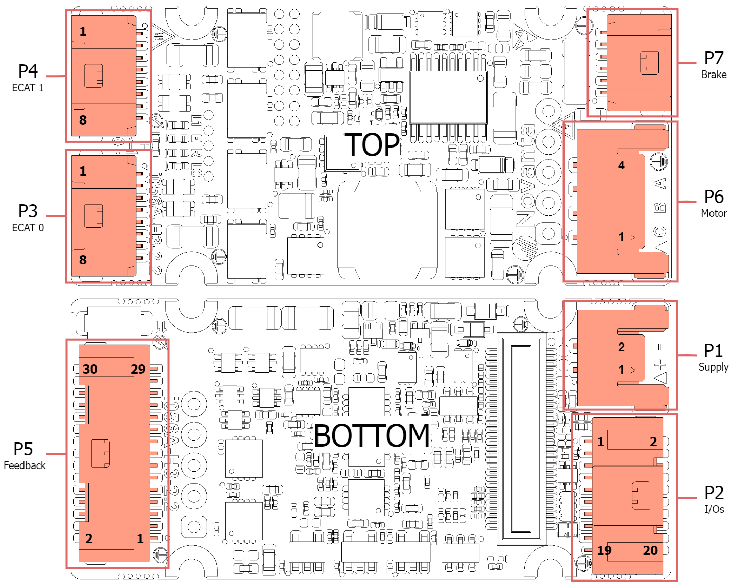
Connector overview
Supply Connector
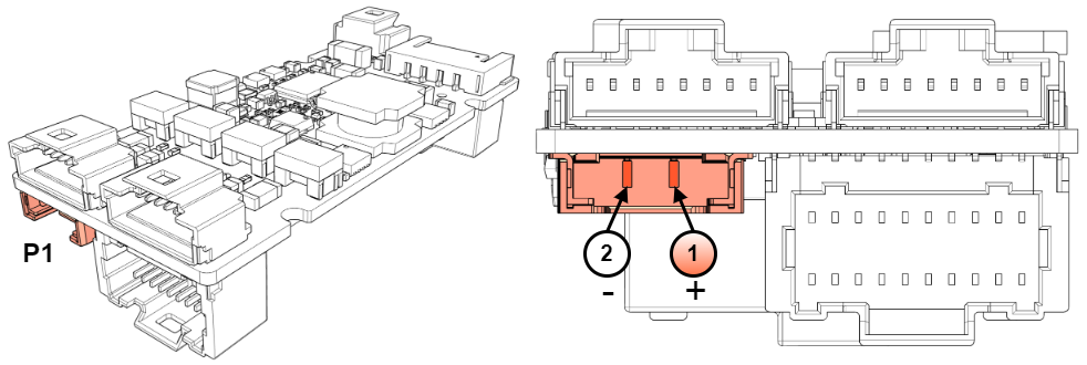
P1 Connector | |||
|---|---|---|---|
2-pin Molex Pico-Lock PCB gold-plated right-angle header. Molex 2053380002. | |||
Pin | Signal | Function | Warning! Risk of electric shock! |
1 | +V_BUS | Power supply positive |  |
2 | GND_P | Power supply return. Internally connected to GND_D. | |
Notes | |||
Warning, power supply, and motor terminals can have dangerous voltages above 50 V. Never touch them directly while in operation. The end installation must ensure that these terminals are not accessible. The recommended section wire is 0.5 mm² to 0.34 mm², or 20 AWG to 22 AWG. Use high-temperature cables with a working temperature ≥ 105ºC. See more details in the Power Supply and Motor Power section of the Denali XCR Product Manual. | |||
Inputs / Outputs and CAN Connector
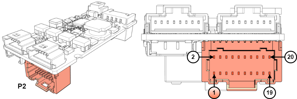
P2 connector | ||
|---|---|---|
20-pin, 2-row Pico-Clasp 1 mm pitch gold-plated right-angle header. Molex 5015712007. | ||
Pin | Signal | Function |
1 | +5V_I/O | +5 V 60 mA output, can be used for peripherals such as switches, I/Os. |
2 | GND_D | Digital signal ground. |
3 | IN1 | Digital input 1: 3.3 V logic levels, tolerant to 6 V continuous, can be used with 5 V logic. |
4 | AN2- | Analog input 2 negative: (±10 V range). Connect to GND if a single-ended analog input is used. |
5 | IN2 | Digital input 2: 3.3 V logic levels, tolerant to 6 V continuous, can be used with 5 V logic. |
6 | AN2+ | Analog input 2 positive: (±10 V range). 16-bit resolution, 0.34425 mV/ADC count. +10 V → 61817 ADC counts. 0 V → 32768. -10 V → 3719 ADC counts. |
7 | OUT1 | Digital output 1: (3.3V levels). |
8 | DNC | Reserved. Do not connect (leave floating). |
9 | OUT2 | Digital output 1: (3.3V levels). |
10 | AN1- | Analog input 1 negative: (±10 V range). Connect to GND if a single-ended analog input is used. |
11 | AN_OUT | Analog output 3.3V levels. |
12 | AN1+ | Analog input 1 positive: (±10 V range). 16-bit resolution, 0.34425 mV/ADC count. +10 V → 61817 ADC counts. 0 V → 32768. -10 V → 3719 ADC counts. |
13 | BOOT | This pin can be pulled down to GND_D to force enter boot mode during power-up in FTP mode. Typically not necessary. If not used, always leave it unconnected. |
14 | NC | Not connected. |
15 | GND_D | Digital signal ground. |
16 | GND_D | Digital signal ground. |
17 | CAN_L | CAN bus line dominant low. Pins 17 and 18 are internally connected and can be useful for daisy-chain wiring. |
18 | CAN_L | |
19 | CAN_H | CAN bus line dominant high. Pins 19 and 20 are internally connected and can be useful for daisy-chain wiring. |
20 | CAN_H | |
EtherCAT and Safety Connectors
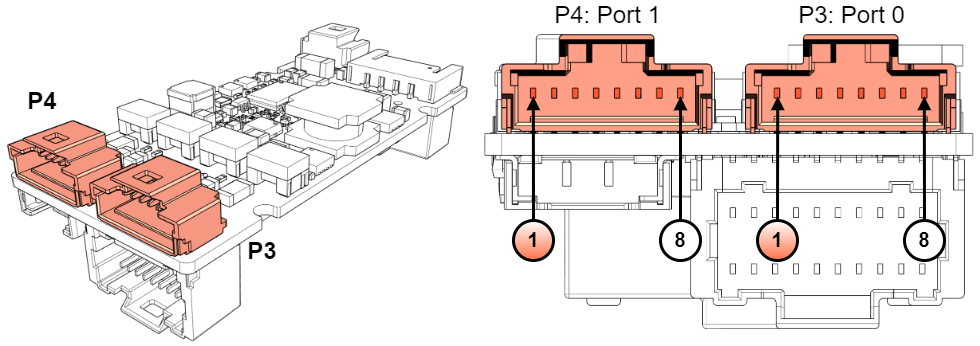
P3 & P4 connectors | ||||
|---|---|---|---|---|
8-pin Pico-Clasp 1 mm pitch gold-plated right-angle header. Molex 2035580807. | ||||
Pin | Signal | Function | Suggested pinout M12-4 D-coded industrial Ethernet | Suggested pinout RJ45 LAN connector |
1 | \STO_A | Safe Input A for STO (positive, active from 15 V to 30 V, ISOLATED). Internal bypass from P3 to P4. | - | - |
2 | STO_RETURN | Safe Inputs Return common (optocoupler LEDs cathode, ISOLATED). Internal bypass from P3 to P4. | - | - |
3 | \STO_B | Safe Input B for STO and SCB (positive, active from 15 V to 30 V, ISOLATED). Internal bypass from P3 to P4. | - | - |
4 | TX_D+ | Transmit Data+ line. Color typ.: White - Orange | 1 | 1 |
5 | TX_D- | Transmit Data- line. Color typ.: Orange | 3 | 2 |
6 | RX_D+ | Receive Data+ line. Colour typ.: White - Green | 2 | 3 |
7 | RX_D- | Receive Data- line. Colour typ.: Green | 4 | 6 |
8 | GND_ETH/PE | Connection for the EtherCAT cable shield. This pin is directly connected to the chassis of the drive - PE. It is recommended to use a cable shield termination with the same properties as TE S02-16-R. | Housing / Shield | Shroud / Shield |
Note | ||||
Both network connectors have the same pinout, thanks to auto-negotiation there is no need to make crossed cables. I.e. TX+ of one device can be connected to the TX+ of another. Note that port 0 should be used as EtherCAT IN and port 1 as EtherCAT OUT. The safety signals are bypassed between connectors P3 and P4 to facilitate the daisy chain connection of communications and safety signals. Find more information in the Communications section of the Denali XCR Product Manual. | ||||
Feedback Connector
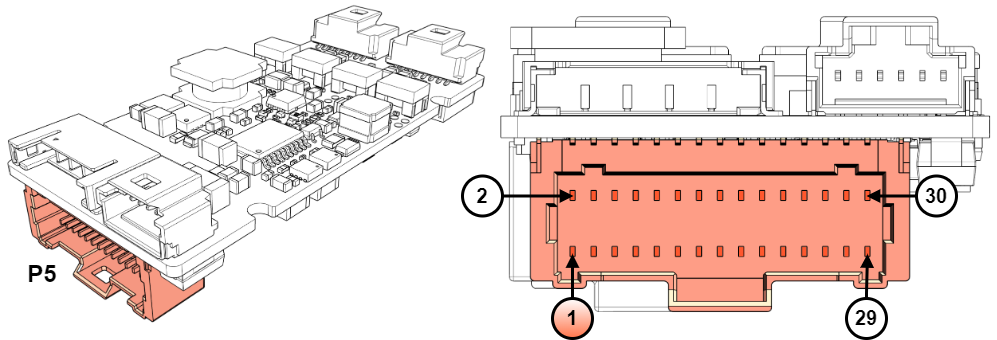
P5 connector | ||
|---|---|---|
30-pin, 2-row Pico-Clasp 1 mm pitch gold-plated right-angle header. Molex 5015713007. | ||
Pin | Signal | Function |
1 | GND_D | Digital ground. |
2 | MOTOR_TEMP_RET | Motor temperature sensor return (referred to as GND_D). Do not use this pin as GND for any other purpose than the negative for motor temperature sensing. |
3 | ENC_Z- | Differential digital incremental encoder index- input. Leave unconnected if using single-ended encoders. |
4 | MOTOR_TEMP_IN | Motor temperature sensor input. A 1.65 kΩ pull-up resistor to 3.3 V is included on the drive. |
5 | ENC_Z+ | Differential digital incremental encoder index+ input. |
6 | GND_D | Digital ground. |
7 | ENC_B- | Differential digital incremental encoder B- input. Leave unconnected if using single-ended encoders. |
8 | HALL_3 | Digital hall sensor 3 input, 1 kΩ pullup to 3.3 V included in the drive. |
9 | ENC_B+ | Differential digital incremental encoder B+ input. |
10 | HALL_2 | Digital hall sensor 2 input, 1 kΩ pullup to 3.3 V included in the drive. |
11 | ENC_A- | Differential digital incremental encoder A- input. Leave unconnected if using single-ended encoders. |
12 | HALL_1 | Digital hall sensor 1 input, 1 kΩ pullup to 3.3 V included in the drive. |
13 | ENC_A+ | Differential digital incremental encoder A+ input. |
14, 15, 16 | NC | Not Connected. |
17, 18, 19, 20 | +5V_FB | 5V 400 mA power supply output for feedback. |
21 | ABS1_CLK- | Absolute encoder 1 CLK negative signal output. For single-ended absolute encoders with TTL or CMOS levels leave this pin floating and connect the clock to ABS1_CLK+. |
22 | ABS2_CLK- | Absolute encoder 2 CLK negative signal output. For single-ended absolute encoders with TTL or CMOS levels leave this pin floating and connect the clock to ABS2_CLK+. |
23 | ABS1_CLK+ | Absolute encoder 1 CLK positive signal output. |
24 | ABS2_CLK+ | Absolute encoder 2 CLK positive signal output. |
25 | ABS1_DATA- | Absolute encoder 1 DATA negative signal input. For single-ended absolute encoders with TTL or CMOS levels leave this pin floating and connect the signal to ABS1_DATA+. |
26 | ABS2_DATA- | Absolute encoder 2 DATA negative signal input. For single-ended absolute encoders with TTL or CMOS levels leave this pin floating and connect the signal to ABS2_DATA+. |
27 | ABS1_DATA+ | Absolute encoder 1 DATA positive signal input. |
28 | ABS2_DATA+ | Absolute encoder 2 DATA positive signal input. |
29, 30 | GND_D | Digital ground. |
Motor Connector
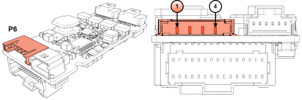
P6 connector | |||
|---|---|---|---|
4-pin Molex Pico-Lock 2.0 PCB gold-plated right-angle header. Molex 2053380004. | |||
Pin | Signal | Function | Warning! Risk of electric shock! |
1 | PH_C | Motor phase C | |
2 | PH_B | Motor phase B | |
3 | PH_A | Motor phase A | |
4 | PE | Protective earth connection, internally connected to standoffs and drive housing. | |
Notes | |||
Warning, power supply, and motor terminals can have dangerous voltages above 50 V and cause electric shock. Never touch them directly while in operation. The end installation must ensure that these terminals are not accessible. Recommended section wire is s 0.5 mm² to 0.34 mm², or 20 AWG to 22 AWG. High-temperature materials are necessary (≥ 100 ºC). | |||
Brake Connector
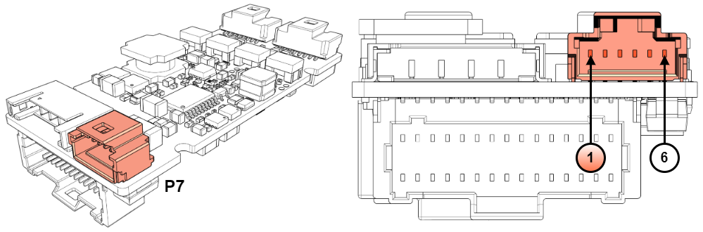
P7 connector | |||
|---|---|---|---|
6-pin Pico-Clasp 1 mm pitch gold-plated right-angle header. Molex 2035580607. | |||
Pin | Signal | Function | Warning! Risk of electric shock! |
1 | +V_BUS | DC bus voltage of the drive. Connect to pin 2 BRAKE_SUPPLY (jumper) to power the brake from the power supply | |
2 | BRAKE_SUPPLY | Brake power supply voltage. Connect to pin 1 if the brake power supply voltage is the same as the motor. Connect to the positive of an external power supply if the brake requires a different voltage. | |
3, 4 | GND_P | Power supply negative. Connect to the negative of an external brake power supply if the brake requires a voltage other than the motor power. | |
5 | BRAKE_OUT_P | Positive Brake output. | |
6 | BRAKE_OUT_N | Negative Brake open-drain output. PWM-capable to modulate the excitation applied to the brake. | |
Notes | |||
Warning, brake terminals can have dangerous voltages above 50 V and cause electric shock. Never touch them directly while in operation. | |||
Mating Connector
P1 mating connector | |
Description | Molex Pico-Lock 2.0 mm pitch 2 positions. |
Image |  |
Part number | Molex 2053410202 |
P2 mating connector | |
Description | Molex Pico-Clasp™ 1.0 mm pitch 20 positions dual row receptacle with locking ramp |
Image | 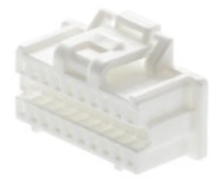 |
Part number | Molex 5011892010 |
P3 and P4 mating connectors | |
Description | Molex Pico-Clasp™ 1.0 mm pitch 8 positions single row receptacle with locking ramp |
Image | 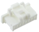 |
Part number | Molex 5013300800 |
P5 mating connector | |
Description | Molex Pico-Clasp™ 1.0 mm pitch 30 positions dual row receptacle with locking ramp |
Image | 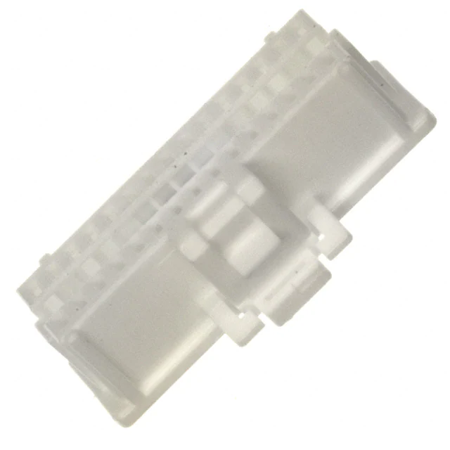 |
Part number | Molex 5011893010 |
P6 mating connector | |
Description | Molex Pico-Lock 2.0 mm pitch 4 positions. |
Image | 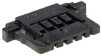 |
Part number | Molex 2053410204 |
P7 mating connectors | |
Description | Molex Pico-Clasp™ 1.0 mm pitch 6 positions single row receptacle with locking ramp |
Image | 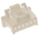 |
Part number | Molex 5013300600 |
Common mating terminals and cables for all signal connectors
All signal connectors are of the Molex Pico-Clasp™ family. All share the same crimp terminals and jumper wires. Given the small size of the connectors, crimping must be done with appropriate tools and application guides provided by Molex. Otherwise, it is strongly recommended to buy pre-crimped jumper wires and connect them to your system using split (or butt) terminals. Spiral wraps are recommended to order and protect the thin wires and make tidy, elegant wiring.
P2, P3, P4, P5, P7 Crimp terminals | |
Description | Molex Pico-Clasp™ crimp socket 28 AWG ~ 32 AWG selective gold plated |
Image |  |
Part number | Molex 5011933000 |
Crimper tool | |
|---|---|
Description | Hand crimper tool 28-32 AWG |
Image |  |
Part number | Molex 638191500 |
P2, P3, P4, P5, P7 Crimped wires 150 mm | |
Description | Molex Pico-Clasp™ 28 AWG black jumper lead socket to socket 150 mm length. Gold plated. |
Image |  |
Part number | Molex 0797581016 |
P2, P3, P4, P5, P7 Crimped wires 300 mm | |
Description | Molex Pico-Clasp™ 28 AWG black jumper lead socket to socket 300mm length. Gold plated. |
Image | 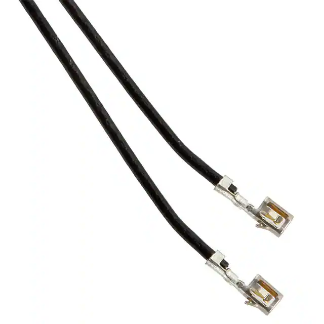 |
Part number | Molex 0797581017 |
Wiring accessory: Spiral wire wrap | |
Description | Nylon spiral wrap abrasion resistant. Internal diameter: 2.41 mm, 3.18 mm expanded | 5.08 mm, 6.35 mm expanded |
Image | 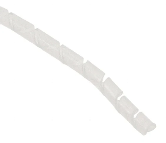 |
Part number | Alpha Wire SW20 NA005 | SW21 NA008 |
Wiring accessory: wire-to-wire solder sleeve | |
Description | Wire to Wire Solder Sleeve Heat shrinkable. Can be used to reliably connect pre-crimped wires to a specific sensor, feedback, or other thin wires. |
Image | 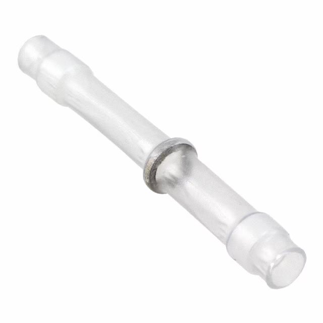 |
TE | B-155-9001 |
Common mating terminals and cables for power connectors
The power connectors are all based on the Molex Pico-Lock™ 2.0 family. Please refer to the Application note to find detailed instructions.
P1 and P6 Crimp terminals | |
Description | Molex Pico-Lock 2.0 crimp socket 20 AWG ~ 22 AWG selective gold plated |
Image |  |
Part number | Molex 2053425028 |
Crimper tool | |
|---|---|
Description | Hand crimper tool Pico-Lock 2.0 20-22 AWG |
Image |  |
Part number | Molex 2133091000 |
Wiring accessory: Spiral wire wrap | |
Description | Nylon spiral wrap abrasion resistant. Internal diameter: 2.41 mm, 3.18 mm expanded | 5.08 mm, 6.35 mm expanded |
Image | |
Part number | Alpha Wire SW20 NA005 | SW21 NA008 |
Wiring accessory: wire-to-wire solder sleeve | |
Description | Wire to Wire Solder Sleeve Heat shrinkable. Can be used to reliably connect pre-crimped wires to a specific sensor, feedback, or other thin wires. |
Image | |
TE | B-155-9001 |